AED 28.35
Description
The Accelerometer Gyroscope Sensor GY-50 L3G 4200D is a 3-axis sensor module that can measure both linear acceleration and angular velocity. It combines an accelerometer and a gyroscope to provide accurate motion detection in three dimensions. This module is commonly used in various applications such as robotics, drones, and virtual reality systems. It communicates with microcontrollers using I2C communication protocol and requires an external power supply.
Package Includes:
- 1 x Accelerometer Gyroscope Sensor GY-50 L3G 4200D
Features:
- Three selectable full scales of 250/500/2000 DPS, allowing for versatile motion detection and measurement options.
- I2C/SPI digital output interface for easy integration with microcontrollers and development boards.
- 16-bit-rate value data output for precise and accurate measurement.
- 8-bit temperature data output to monitor the temperature of the module.
- Two digital output lines, including interrupt and data ready, trigger certain actions in response to specific events.
- Ultra-stable over temperature and time, providing consistent and reliable measurement results.
- A wide supply voltage of 3.3v - 5V makes it suitable for various projects and applications.
- Embedded FIFO (first-in, first-out) buffer to store and retrieve data in a timely manner.
- Extended operating temperature range of -40 ℃ to +85 ℃, allowing for use in harsh environments.
- Compact size with dimensions of 16 x 17mm, making it easy to incorporate into your project or device.
Description:
The gyroscope module is a compact, high-performance sensor that measures rotational velocity in three axes. It features three selectable full scales of 250/500/2000 DPS, allowing for versatile motion detection and measurement options. The module communicates with microcontrollers and development boards using either an I2C or SPI digital output interface, making it easy to integrate into your projects. The module outputs 16-bit-rate value data for precise and accurate measurement, as well as 8-bit temperature data to monitor the temperature of the module. It also includes two digital output lines, including interrupt and data ready, that can be used to trigger certain actions in response to specific events. The gyroscope module is ultra-stable over temperature and time, providing consistent and reliable measurement results. It also has a wide supply voltage of 2.4-3.6V, making it suitable for a variety of projects and applications. The embedded FIFO buffer allows for efficient data storage and retrieval. This gyroscope module has an extended operating temperature range of -40 ℃ to +85 ℃, making it ideal for use in harsh environments. It is compact with dimensions of 16 x 17mm, making it easy to incorporate into your project or device.
Principle of Work:
The gyroscope module works based on the principle of Coriolis acceleration. Inside the module, there is a sensing element or MEMS (microelectromechanical system) that consists of a vibrating structure that oscillates in a specific direction. When the gyroscope is rotated in a different direction, the Coriolis acceleration causes the sensing element to deflect in a direction perpendicular to the axis of rotation. This deflection generates a proportional electrical signal that can be measured and used to determine the rotational velocity and direction. To calculate the angular velocity of the module, the sensing element is designed to oscillate in all three axes. The module can measure the deflection of the sensing element in each of the three axes, allowing it to calculate the rotational velocity in each axis. The gyroscope module also includes a temperature sensor to monitor the temperature of the sensing element. This is important because temperature changes can affect the accuracy and stability of the gyroscope. The gyroscope module communicates with a microcontroller or development board using either an I2C or SPI digital output interface. The module outputs 16-bit-rate value data and 8-bit temperature data, which can be used to determine the angular velocity and temperature of the module, respectively. The gyroscope module also includes an embedded FIFO buffer that stores data and allows for efficient data retrieval. The module can operate in different power modes to optimize power consumption and data rate.
Pinout of the Module:
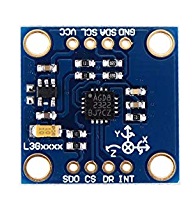
- VCC - Power supply (2.4-3.6V): This pin supplies power to the module.
- GND - Ground: This pin is connected to the ground.
- SDA - Serial Data line (I2C interface): This pin is used for bi-directional data transfer between the gyroscope module and the microcontroller or development board using the I2C interface.
- SCL - Serial Clock line (I2C interface): This pin is used for clock synchronization between the gyroscope module and the microcontroller or development board using the I2C interface.
- CS - Chip Select (SPI interface): This pin is used for selecting the gyroscope module when using the SPI interface.
- SDO - Serial Data Output (SPI interface): This pin outputs data from the module when using the SPI interface.
- INT1 - Interrupt Output 1: This pin is an interrupt output that is triggered when a user-defined threshold is exceeded or when data is ready.
- DR - Data Ready Output: This pin is used to indicate that new data is ready to be read from the module.
Applications:
- Robotics: The gyroscope module is used in robotics applications to measure the angular velocity and orientation of the robot. This information can be used to control the robot's movements and to keep it stable.
- Drones: The module is used in drones to measure orientation, stabilize the drone, and control its movements.
- Gaming: The gyroscope module is used in gaming applications to measure the movement of the player's device and to use that information to control the game.
- Navigation: The module can be used in navigation applications to measure the orientation and movement of the device and to use that information to calculate its position and movement.
- Industrial control: The gyroscope module is used in industrial control applications to measure the rotation rate of machines and equipment, such as motors and conveyor belts, and to use that information to control their movements.
- Virtual reality: The module is used in virtual reality applications to track the movement of the user's head and to use that information to control the virtual environment.
Circuit:
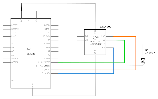
- Connect GND to GND on the Arduino board.
- Connect VCC to 5V on the Arduino board.
- Connect SDA to A4 on the Arduino board.
- Connect SCL to A5 on the Arduino board.
- Connect the cathode (-) of the IN5817 diode to the SDA pin.
- Connect the anode (+) of the IN5817 diode to pin 11 on the Arduino board.
Library:
No library installation needed
Code:
The code initializes and configures a 3-axis gyroscope module using SPI communication protocol. The gyroscope module measures angular velocity in three dimensions and outputs the data in the form of digital values. The code configures the gyroscope by writing values to various control registers using SPI commands, and then reads the angular velocity data from the module and converts it to degrees per second.
#include "SPI.h"

const int CS_Pin = 10;
const float K = 8.75;

void setup() {
  Serial.begin(115200);
  pinMode(CS_Pin, OUTPUT);
  digitalWrite(CS_Pin, HIGH);
  SPI.begin();
  SPI.setBitOrder(MSBFIRST);
  SPI.setDataMode(SPI_MODE3);
  configureGyroscope();
}

void loop() {
  int x = readAxis(0x28);
  int y = readAxis(0x2A);
  int z = readAxis(0x2C);
  Serial.println(String(K*x)+" "+String(K*y)+" "+String(K*z));
  delay(10);
}

void configureGyroscope() {
  writeRegister(0x21, 0x09);
  writeRegister(0x23, 0x80);
  writeRegister(0x20, 0xEF);
}

int readAxis(byte address) {
  digitalWrite(CS_Pin, LOW);
  SPI.transfer(0xE8);
  SPI.transfer(address);
  int value = SPI.transfer(0) | (SPI.transfer(0) << 8);
  digitalWrite(CS_Pin, HIGH);
  return value;
}

void writeRegister(byte address, byte value) {
  digitalWrite(CS_Pin, LOW);
  SPI.transfer(address);
  SPI.transfer(value);
  digitalWrite(CS_Pin, HIGH);
}
- The program starts by including the SPI library and defining the CS_Pin (chip select) as pin 10. Then, it initializes the serial communication and sets the CS_Pin as an output pin. After that, it initializes the SPI communication and sets the bit order and data mode.
- The program then sends commands to the accelerometer to configure its registers. These commands set the high-pass filter mode and cut-off frequency, the data rate, bandwidth, and other settings. Once the accelerometer is configured, the program enters the main loop.
- In the main loop, the program reads the acceleration data from the accelerometer using the SPI communication protocol. It sends the address of the LSB (least significant byte) of the X-axis acceleration data and then reads 6 bytes of data (2 bytes for each axis) from the accelerometer. The program then converts the raw acceleration data into meaningful values by multiplying it by a scaling factor (K). Finally, it prints the acceleration values along the X, Y, and Z axes to the serial monitor, which can be displayed on a computer.
- The program repeats this process every 10 milliseconds, continuously reading the acceleration data from the accelerometer and printing it to the serial monitor.
Technical Details:
- Sensor: L3G4200D three-axis digital gyroscope
- Measurement range: ±250, ±500, or ±2000 degrees per second (dps)
- Sensitivity: 8.75, 17.5, or 70 LSB (Least Significant Bit) per degree per second, depending on the range selected
- Resolution: 16 bits
- Output data rate: 100, 200, 400, 800 Hz (configurable)
- Interface: I2C/SPI digital output interface supports up to 400 kHz data rates
- Supply voltage: 3.3 to 5 VDC
- Operating temperature range: -40°C to +85°C
- Dimensions: 16 x 17mm
- Weight: 2.9 g
Resources:
Comparisons:
The MPU6050 and GY-50 L3G4200D are both commonly used gyroscope and accelerometer modules for measuring motion and orientation in electronic projects. Here are some comparisons between the two modules:
- Measurement range: The MPU6050 has a wider measurement range of ±250, ±500, ±1000, and ±2000 degrees per second (dps) for gyroscope and ±2g, ±4g, ±8g, and ±16g for the accelerometer, while the GY-50 L3G4200D has a narrower range of ±250, ±500, and ±2000 dps for gyroscope and ±2g for accelerometer.
- Resolution: The MPU6050 has a higher resolution than the GY-50 L3G4200D. It can measure angular velocity with a resolution of up to 131 LSB (least significant bit) per dps, while the GY-50 L3G4200D has a resolution of up to 70 LSB per dps.
- Noise performance: The MPU6050 has a lower noise performance than the GY-50 L3G4200D. This means that the MPU6050 is less susceptible to noise and can provide more accurate readings.
- Power consumption: The GY-50 L3G4200D has a lower power consumption than the MPU6050. It typically consumes around 6 mA during operation, while the MPU6050 consumes around 10 mA.
The MPU6050 has a wider measurement range, higher resolution, and lower noise performance, but consumes more power and is generally more expensive than the GY-50 L3G4200D. The GY-50 L3G4200D, on the other hand, has a narrower measurement range, lower resolution, and higher noise performance, but consumes less power and is generally cheaper. The choice between the two modules would depend on the specific requirements of the project.