AED 23.10
Description
The MAX9814 module is a versatile audio component that incorporates both an amplifier circuit and a high-quality built-in microphone. Its primary function is to detect sounds through the microphone and generate an analog signal accordingly. Additionally, the module offers the convenience of being directly connected to an AUX output, allowing for seamless integration into various audio systems. This feature makes it a practical choice for applications requiring sound detection and amplification capabilities while providing easy connectivity options.
Package Includes:
- 1x Microphone Sound Detector Module MAX9814
Features:
- Integrated Amplifier: The module includes a built-in amplifier circuit, eliminating the need for an external amplifier component. This simplifies the setup and reduces the required circuitry.
- High-Quality Microphone: It features a high-performance built-in microphone that is designed to capture clear and accurate sound signals. This ensures reliable and precise audio detection.
- Analog Signal Output: When a sound is detected by the microphone, the module generates an analog signal as an output. This signal can be further processed or used directly for various applications.
- AUX Output Compatibility: The module is designed to be directly connected to an AUX output. This makes it compatible with a wide range of audio systems, allowing for seamless integration and versatility in different setups.
- Low Noise: The module is designed to minimize noise interference, ensuring clear and high-fidelity audio recordings or sound detection.
- Low Power Consumption: It operates efficiently, consuming minimal power, which benefits devices that rely on battery power or energy-efficient designs.
- Versatility: The module is well-suited for a wide range of electronic products, making it adaptable to various applications and projects.
- Automatic Gain Control (AGC): The AGC feature automatically adjusts the microphone's amplification to optimize the audio levels, providing consistent and balanced output even in varying sound environments.
- Programmable Attack Time: Users have the flexibility to program the attack time, allowing for precise control over how quickly the module responds to changes in audio levels.
- Three Gain Settings: The module offers three gain settings (40dB, 50dB, 60dB), enabling users to select the appropriate amplification level based on their specific requirements.
- Programmable Attack and Release Ratio: Users can program the attack and release ratio to fine-tune the module's response to sudden sound changes, achieving customized audio processing.
Description:
The MAX9814 is an exceptional high-end microphone amplifier module designed to meet your audio needs with precision and versatility. Equipped with a high-quality 20-20kHz electret condenser microphone (ECM), this module ensures accurate sound capture across a wide frequency range. The MAX9814 offers a range of setup options to tailor its performance to your requirements. Emitting a reliable analog signal, it allows for seamless integration into your audio system. By default, the module is set to a maximum gain of 60dB, providing ample amplification. However, you have the flexibility to decrease the gain to 40dB or 50dB simply by connecting the Gain pin to Vdd or GND, giving you fine control over the amplification level. In addition, the module enables you to customize the Attack/Release (AR) ratio. The default ratio of 1:4000 can be adjusted to either 1:2000 or 1:500, allowing for precise modulation of the audio response. To ensure optimal performance, the module operates with a bias of 1.25V DC, resulting in a robust audio signal output of approximately 2Vpp. Furthermore, its direct compatibility with AUX outputs simplifies the integration process, making it suitable for a wide variety of audio setups and systems.
Principle of Work:
The MAX9814 module consists of an amplifier circuit and an electret condenser microphone (ECM). The ECM captures sound waves and converts them into electrical signals. These signals are then processed by the amplifier circuit, which amplifies the audio signals to a desired level. As for the protocol used, the MAX9814 module typically operates using analog signals. It does not rely on any specific digital communication protocol such as I2C or SPI. Instead, it provides an analog output that can be directly connected to an analog input of a microcontroller or audio device.
To work with the MAX9814 module using a microcontroller:
- Power Supply: Connect the power supply (usually +3.3V or +5V) to the appropriate pins of the MAX9814 module, ensuring proper voltage levels are provided.
- Analog Connection: Connect the analog output pin of the MAX9814 module to an analog input pin of the microcontroller or audio device. This allows the microcontroller to receive the amplified audio signal.
- Gain Configuration: If desired, adjust the gain settings of the MAX9814 module by connecting the Gain pin to Vdd or GND, as specified in the module's datasheet. This allows you to customize the amplification level based on your requirements.
- Optional: If you want to modify the Attack/Release (AR) ratio, refer to the module's datasheet for instructions on changing this parameter. This step is optional and may not be necessary for all applications.
- Microcontroller Integration: In your microcontroller code, read the analog input connected to the MAX9814 module to receive the amplified audio signal. You can then process, analyze, or utilize the audio data as per your project requirements.
Pinout of the Module:
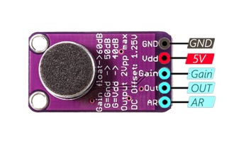
- VCC: This pin is used to supply power to the module and requires a voltage range of 2.7V to 5.5V.
- GND: This pin is connected to the ground and serves as the reference for the module's electrical signals.
- OUT: The OUT pin provides the analog data output from the module to be received by the microcontroller or audio device for further processing.
- Gain: The Gain pin allows adjustment of the maximum output of the module. Depending on its connection, different gain settings can be achieved:
- When the Gain pin is disconnected, the module operates at a gain of 60 dB.
- Connecting the Gain pin to VCC sets the gain to 50 dB.
- Connecting the Gain pin to GND sets the gain to 40 dB.
-
AR: The AR pin enables adjustment of the module's accuracy, specifically the Attack/Release (AR) ratio. The default AR ratio is 1:4000. However, the AR pin can be connected to different configurations to achieve alternative ratios:
- When the AR pin is disconnected, the default ratio of 1:4000 is maintained.
- Connecting the AR pin to VCC changes the AR ratio to 1:2000.
- Connecting the AR pin to GND changes the AR ratio to 1:500.
By manipulating the Gain and AR pins' connections, users can fine-tune the module's performance to suit their specific application requirements, adjusting the output gain and accuracy as desired.
Applications:
- Noise Detectors: The module's sensitivity and amplification make it suitable for noise detection systems. It can be used to monitor environmental noise levels, detect specific sounds, or trigger alerts in response to noise thresholds.
- Voice Control Modules: With its built-in microphone and amplifier, the module is ideal for voice control applications. It can be integrated into devices that utilize voice commands, such as smart speakers, voice-activated assistants, or home automation systems.
- Sound Recorders: The MAX9814 module's ability to capture and amplify audio signals makes it well-suited for sound recording devices. It can be utilized in voice recorders, audio loggers, or any application that requires accurate and high-quality audio recording.
- Activity Monitors: The module's sensitivity to sound enables its use in activity monitoring systems. It can be employed to detect specific sounds or patterns indicative of activities, such as baby monitoring devices, security systems, or occupancy sensing applications.
Circuit:
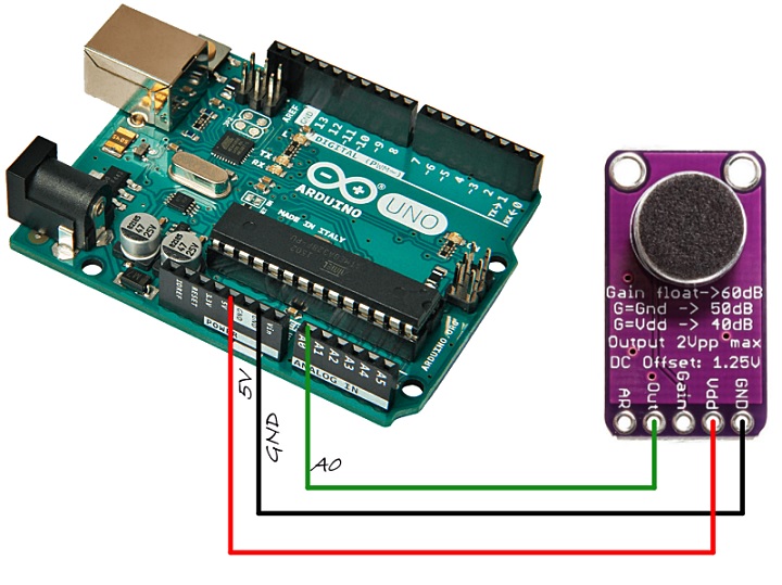
- Power Connection: Connect the GND (ground) pin of the module to the GND pin of the Arduino. This establishes the common ground reference between the module and the Arduino. Additionally, connect the 5V pin of the module to the 5V pin of the Arduino, providing power to the module.
- Analog Output Connection: Connect the analog output pin of the module to the A0 (analog input) pin of the Arduino. This allows the Arduino to receive the analog signal from the module and process it as required.
Library:
This Module doesn't need a library to work.
Code:
This code collects analog input samples within a specified window duration. It finds the maximum and minimum values of the samples to calculate the sound amplitude. The amplitude is then converted to a voltage value and printed via the serial monitor.
const int micPin = A0;
const int sampleWindow = 50; // Window width in milliseconds (50 ms = 20 Hz)

void setup() {
  Serial.begin(9600); // Initialize serial communication at 9600 baud rate
}

void loop() {
  unsigned int maxSignal = 0;
  unsigned int minSignal = 1024;

  // Collect samples within the window
  unsigned long startTime = millis(); // Record the starting time
  while (millis() - startTime < sampleWindow) { // Perform the loop for the duration of the sample window
    unsigned int sample = analogRead(micPin); // Read the analog input

    if (sample < 1024) {
      // Update the maximum and minimum signal values
      if (sample > maxSignal)
        maxSignal = sample;
      else if (sample < minSignal)
        minSignal = sample;
    }
  }

  unsigned int peakToPeak = maxSignal - minSignal; // Calculate the sound amplitude
  double voltage = (peakToPeak * 5.0) / 1024; // Convert the amplitude to voltage

  Serial.println(voltage); // Output the voltage value
}
- It begins by defining the pin connected to the microphone as
micPin, which is set toA0(analog input pin 0) in this case. ThesampleWindowvariable specifies the duration of the sampling window in milliseconds. - In the
setup()function, the code initializes the serial communication at a baud rate of 9600. This enables communication with external devices or software via the serial port. - The
loop()function is where the main execution of the code occurs. It repeatedly runs in an infinite loop. - Within the loop, two unsigned integer variables,
maxSignalandminSignal, are initialized.maxSignalis set to 0 to store the maximum signal value, whileminSignalis set to 1024, representing the maximum analog input value, as an initial placeholder for the minimum signal value. - A while loop is executed, collecting samples from the analog input pin (
micPin) for the specifiedsampleWindowduration. Themillis()function is used to keep track of the elapsed time. The loop runs until the elapsed time exceeds thesampleWindow. - Inside the while loop, the code reads the analog input value from the microphone using
analogRead(micPin). The sample value is stored in thesamplevariable. - The code checks if the sample value is less than 1024, which ensures valid readings within the analog input range.
- If the sample value is valid, the code updates the
maxSignalandminSignalvariables accordingly. If the current sample value is greater thanmaxSignal, it replaces the previous maximum value. Similarly, if the sample value is smaller thanminSignal, it replaces the previous minimum value. - After the sample collection is complete, the code calculates the sound amplitude by subtracting the minimum signal value (
minSignal) from the maximum signal value (maxSignal), storing it in thepeakToPeakvariable. - The code then converts the amplitude to a voltage value using the formula
(peakToPeak * 5.0) / 1024, where 5.0 represents the maximum voltage range of the analog input and 1024 is the maximum analog input value. - Finally, the voltage value is sent to the serial port using
Serial.println(voltage), allowing it to be displayed in the serial monitor or transmitted to external devices for further analysis or processing.
Technical Details:
- 2.7V to 5.5V Supply Voltage Range
- Low Input-Referred Noise Density of 30nV/√Hz
- Low THD: 0.04% (typical)
- Low-Power Shutdown Mode
- Internal Low-Noise Microphone Bias, 2V
- -40°C to +85°C Extended Temperature Range
Resources:
Comparisons:
The MAX9814 is the top choice for high-fidelity audio projects, providing precise and reliable signal amplification. The MAX4466 offers adjustable gain but lacks automatic gain adjustment. The SPW2430, although compact and excellent for audio detection, may have limitations in handling powerful audio signals:
-
MAX9814:
- The superior choice for high-fidelity audio applications
- Provides a more precise and logical audio signal compared to analog-to-digital converter circuits
- Features automatic gain adjustment for optimal signal amplification
- Ensures consistent and accurate amplification across various audio sources
-
MAX4466:
- Conventional option with built-in operational amplifier (op-amp)
- Adjustable gain ranging from 25x to 125x
- Lacks automatic gain adjustment found in the MAX9814
-
SPW2430:
- Compact module specialized in audio detection
- Excels in accurately detecting and analyzing audio signals
- Features a 0.67V DC bias and approximately 100mVpp output peak-to-peak voltage
- May experience clipping or distortion when exposed to powerful or loud noises