AED 13.75
Description
This versatile sensor is designed to detect rain, snow, and water with its single-sided, high-conductivity copper plate. Operating in a wide voltage range (3.3V to 5V), it offers both digital (0 or 1) and analog voltage outputs, providing flexibility for various applications. The sensor features adjustable sensitivity through a potentiometer, ensuring optimal performance.
Features:
- Wide Voltage Range: Operates on 3.3V to 5V power supply.
- Digital and Analog Outputs: Provides digital (0 or 1) and analog voltage outputs for versatile applications.
- Adjustable Sensitivity: Fine-tune the sensor's sensitivity using a potentiometer for optimal performance.
- Direct Control of Devices: Capable of driving relays, buzzers, and small fans (up to 100mA) without additional components.
- Easy Installation: Fixed bolt hole and a separate control panel for convenient wiring.
- LED Indicators: Shows power and output status for easy monitoring.
- Large Rain Plate: Increases detection area for enhanced accuracy.
- Compact Size: Small PCB board (3.2cm x 1.4cm) saves space during installation.
- Wide-Voltage Comparator: Utilizes an LM393 comparator for versatile operation.
How it Works:
- Connect the sensor to a 5V power supply; the power indicator light will turn on.
- When the rain plate is dry, the DO (digital output) is high, and the LED indicator turns off.
- Upon contact with a water droplet, the DO goes low, and the LED indicator turns on.
- Wiping off the water restores the DO to high, turning off the LED again.
Outputs:
| Output Type | Description |
|---|---|
| AO (Analog Output) | Connect to a microcontroller's AD port to measure the size of water droplets on the plate. |
| DO (Digital Output) | Connect to a microcontroller to detect the presence of rain or water. |
Connection Pins:
| Pin | Description |
|---|---|
| VCC | Positive power supply (3-5V) |
| GND | Ground |
| DO | TTL digital output |
| AO | Analog output |
Package Includes:
- 1 x Rain-sensing board
- 1 x Control board
- 2 x Dupont wires
The Control Board
The control board consists of two input pins and four output pins. The input pins are connected to the mainboard and the output pins to your favorite microcontroller, for example, an Arduino Uno or a NodeMCU.
On the control board, you find multiple resistors that also functions are the voltage divider to provide an analog signal for the rain intensity. Therefor as input, we get resistance from the mainboard and the control board converts this resistance into a voltage drop between the analog pin and ground. The microcontroller uses the internal analog to digital converter (ADC) to convert the voltage from the analog pin to a digital value between 0 and 1023 that can be printed to the serial output in your Arduino IDE.
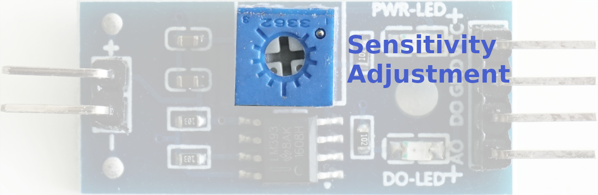
The biggest part on the control board is the potentiometer to adjust the sensitivity of the rain detector. The potentiometer is only a variable resistor whose resistance is changed with the setting wheel at the top. We need this potentiometer to compare the resistance of the potentiometer with the resistance of the mainboard. If the resistance of the raining board is lower than the threshold, defined by the potentiometer, the digital output of the control board changes from 1 HIGH to 0 LOW.
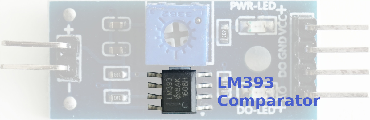
But who does this comparison between the two resistances? This is done by the LM393 comparator because the voltage drop over both resistors is linear to their resistance due to ohms law. The LM393 consists of two independent precision voltage comparators and is specially designed to operate from a single power supply, in our case the microcontroller.
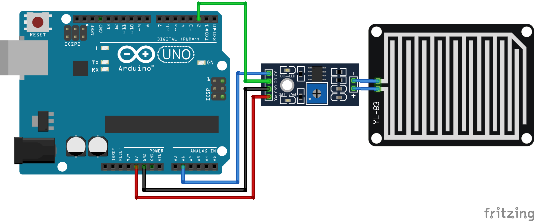
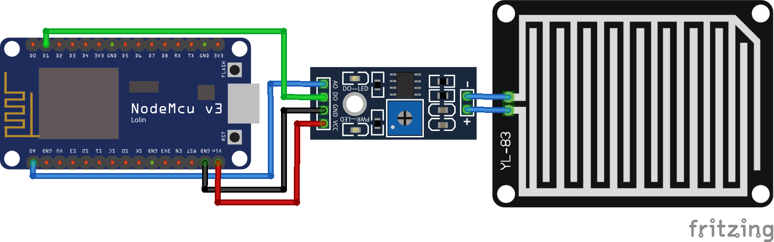
Wiring of the Rain Sensor
The following two pictures show the wiring between the mainboard and the control board as well as the connection between the control board and the Arduino microcontroller and the NodeMCU as ESP8266 based microcontroller. Because the raining board only connects a resistance to the control board, switching the connection does not have any influence.
Examples of the Rain Sensor
- Read-only the analog value and create a time series chart of the analog value.
- Read also the digital value and print the analog and digital value to the serial output.
1- we can use the wiring from the previous picture :
The next code continuously reads the voltage from an analog rain sensor connected to pin A1 and the digital state of a rain switch connected to pin 2. It then prints the voltage reading and a boolean value indicating if it's raining (based on the state of the switch) to the serial monitor for observation:
#define rainAnalog A1
#define rainDigital 2
void setup() {
 Serial.begin(9600);
 pinMode(rainDigital,INPUT);
}
void loop() {
 int rainAnalogVal = analogRead(rainAnalog);
 boolean bIsRaining = !(digitalRead(rainDigital));
 Serial.println(rainAnalogVal);
 delay(200);
}
1. Defining Constants:
#define rainAnalog A1: This line defines a constant namedrainAnalogand assigns it the valueA1.A1likely refers to the analog pin number 1 on your Arduino board.#define rainDigital 2: Similarly, this line defines a constant namedrainDigitaland assigns it the value2, which probably refers to digital pin number 2.
2. Setting Up:
void setup(): This function is called once when the Arduino starts up.Serial.begin(9600): This line initializes serial communication with a baud rate of 9600. This means the Arduino can communicate with your computer at a speed of 9600 bits per second.pinMode(rainDigital, INPUT): This configures the pin specified byrainDigital(which is likely pin 2 in this case) as an input pin. This means the Arduino will read the voltage level on that pin from an external sensor.
3. Looping:
void loop(): This function is called repeatedly after thesetupfunction finishes. This creates a continuous loop where the code inside is executed again and again.int rainAnalogVal = analogRead(rainAnalog): This line reads the voltage level from the analog pin specified byrainAnalog(which is likely pin A1) and stores the value in the integer variablerainAnalogVal.boolean bIsRaining = !(digitalRead(rainDigital)): This line reads the digital state of the pin specified byrainDigital(which is likely pin 2). The!symbol is a logical NOT operator, so it inverts the value. This meansbIsRainingwill betrueif the pin is low (indicating rain) andfalseif the pin is high (indicating no rain).Serial.println(rainAnalogVal): This line prints the value ofrainAnalogVal(the raw voltage reading) to the serial monitor attached to your computer.delay(200): This line pauses the program for 200 milliseconds before repeating the loop.