Out Of Stock
Description
The RobotDYN LDR Light Sensor Module is Used to determine a light source's brightness. The photosensitive resistor module most sensitive to environmental light intensity is often used to measure ambient brightness and light intensity. The module's DO port output is high when the level of ambient light outside crosses a set threshold. In addition, the module has the ability to generate analog signals on A0 that are appropriate for a variety of widely employed microcontrollers, such as Arduino, ESP32, and others.
Package Includes:
- RobotDYN LDR Light Sensor Module with analog & digital outs (RobotDYN)
Features:
- Able to detect ambient brightness and light intensity
- Adjustable sensitivity (via blue digital potentiometer adjustment)
- Operating voltage 3.3V-5V
- Digital switching outputs (0 and 1) -D0
- With fixed bolt hole for easy installation
- Small board PCB size.
- Power indicator
- Features wide range voltage comparator LM393
Description:
The RobotDYN LDR Light Sensor Module is used to determine a light source's brightness. The comparator LM393 features an adjustable sensitivity (through a blue digital potentiometer adjustment) and operates with an input voltage range of 3.3V to 5V. It also includes a fixed bolt-hole for convenient installation. The photosensitive resistor module that is most sensitive to environmental light intensity is often used to measure ambient brightness and light intensity. The module's DO port output is high when the level of ambient light outside crosses a set threshold. In addition, the module has the ability to generate analog signals on A0 that are appropriate for a variety of widely employed microcontrollers, such as Arduino, ESP32, and others.
Principle of Work:
Electrons are responsible for electricity flowing through any metal, and they are classed as insulators, conductors, or semiconductors based on the number of electrons traveling through them at any one time. These are classified based on the band gap, which is the energy difference between the valence and conduction bands. A photoresistor is made of high-resistance semiconductor material since there aren't many electrons available for conduction. The top of the photoresistor is coated with a zigzag pattern of the semiconductor cadmium sulfur. In order to obtain the necessary resistance and power rating, it is placed in this manner. When light strikes the photoresistor, the valence band electrons or valence electrons absorb energy sufficient for them to break their bond with the atom and move to the conduction band.
This process of transfer of electrons generates a current flow to the photoresistor and as more and more electrons transfer to the conduction band, the current flow increases and results in the decrease of resistance in the photoresistor.
Pinout of the Module:
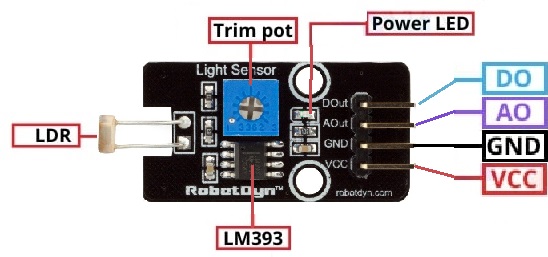
| Module | Description |
|---|---|
| A0 | Analog Pin |
| D0 | Digital Pin |
| VCC | +5V |
| GND | GND |
Applications:
- Detecting the darkness and light.
- Automatic light on/off system
- It is used to measure light intensity.
Circuit:
The sensor pin GND to ground, the sensor pin VCC is connected to VCC, and sensor pin A0 to ANalog pin A0.

Library:
no library is needed.
Code:
The program measures the current voltage value at the sensor,
calculates from this and the known series resistance the current
the resistance value of the sensor and outputs the results to the serial output
int sensorPin = A5; // Declare the input pin here
// Serial output in 9600 baud
void setup()
{
 Serial.begin(9600);
}
void loop()
{
 // Current voltage value is measured...
 int rawValue = analogRead(sensorPin);
 float voltage = rawValue * (5.0/1023) * 1000;
 float resitance = 10000 * ( voltage / ( 5000.0 - voltage) );
 // ... and here output to the serial interface
 Serial.print("Voltage value:"); Serial.print(voltage); Serial.print("mV");
 Serial.print(", resistance value:"); Serial.print(resitance); Serial.println("Ohm");
 Serial.println("---------------------------------------");
 delay(500);
}
We'll start obtaining data on the serial monitor when you upload the code, start the Serial Monitor, direct the sensor to a light source then check the serial monitor for changes
Technical Details:
- Voltage: 3-5V
- Supply Current: 0.5-3mA
- Peak Wavelength: 540 nm
- Ambient temperature: -30~70C
- Features wide range voltage comparator LM393
Resources:
Comparisons:
This module is an easy way to start with a sensor with Arduino, with this module you need no external components like bare-bone LDR because you can't work directly with LDRs without a voltage divider circuit which needs a resister plus an LDR, also this module has a fixed screw hole to fix your module in any DIY project, we don't forget to mention that the module has an analog output and Schmitt trigger which gives a digital output in comparison another module we have on this website like KY-018 which has no comparator and no digital output and can't drive a relay but still this module has an only power indicator and the (LDR Light Sensor Module (Light Dependent Resistor)) has LED power indicator and digital output indicator