AED 26.25
Description
LSM6DS3 is a system-in-package featuring a 3D digital accelerometer and a 3D digital gyroscope performing at 1.25 mA (up to 1.6 kHz ODR) in high-performance mode and enabling always-on low-power features for an optimal motion experience for the consumer. The LSM6DS3 has a full-scale acceleration range of ±2/±4/±8/±16 g and an angular rate range of ±125/±245/±500/±1000/±2000 DPS. The bare-minimum connections required are broken out on the left side of the board. These are the power and I 2 C pins for the communication interface. This product can be used for different applications for tilt, motion, and tap sensings, such as robotics, IoT, and consumer electronics. Please keep in mind that the LSM6DS3 is a 3.3V device so supplying voltages greater than ~3.6V can permanently damage the IC. A logic level shifter is required for any development platform operating at 5V.
Specifications:
- Power consumption: 0.9 mA in combo normal mode and 1.25 mA in combo high-performance mode up to 1.6 kHz. “Always on” experience with low power consumption for both accelerometer and gyroscope.
- Smart FIFO up to 8 bytes based on features set
- ±2/±4/±8/±16 g full scale
- ±125/±245/±500/±1000/±2000 DPS full scale
- Analog supply voltage: 1.71-5V
- SPI/I2C serial interface with main processor data synchronization
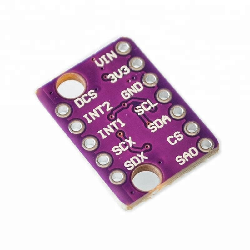
Pinout of the GY-LSM6DS3 Module:
| Pin Label | Pin Function | Notes |
|---|---|---|
| GND | Ground | 0V voltage supply. Spare a GND pin to connect more stuff! |
| VDD | Power Supply | Supply voltage to the chip. It should be regulated between 1.8V and 3.6V. Spare VDD is provided for general use as well. |
| SDA/SDI | I2C: Serial Data SPI: MOSI |
I2C: Serial data (bi-directional) SPI: Device data in (MOSI) |
| SCL | Serial Clock | I2C and SPI serial clock. |
| SDO/SA0 | I2C: Address SPI: MISO |
I2C: Address LSB SPI: Device data out (MISO) |
| CS | I2C: Mode SPI: CS |
I2C: Select I2C (disconnected) SPI: Chip select (Slave select) |
| INT2 | Accel/Gyro Interrupt 2 | INT1 and INT2 are programmable interrupts for the accelerometer and gyroscope. They can be set to alert on over/under thresholds, data ready, or FIFO overruns. Make sure these are connected to an INPUT pin to prevent driving 5v back into the LSM6DS3. |
| INT1 | Accel/Gyro Interrupt 1 | |
| OCS | Aux SPI 3-wire | These pins attach slave I2C and 3-wire devices for FIFO data collection. This function is not covered in this tutorial. |
| SCX | Aux Clock | |
| SDX | Aux Data |
Arduino Code for the GY-LSM6DS3 Module:
first, you will need to download the GY-LSM6DS3 library by clicking here then add it to the Arduino IDE then upload the next code to the Arduino:
#include "Arduino_LSM6DS3.h"
void setup() {
 Serial.begin(9600); // initialize serial bus (Serial Monitor)
 while (!Serial); // wait for serial initialization
 Serial.print("LSM6DS3 IMU initialization ");
 if (IMU.begin()) { // initialize IMU
 Serial.println("completed successfully.");
 } else {
 Serial.println("FAILED.");
 IMU.end();
 while (1);
 }
 Serial.println();
}
void loop() {
 char buffer[8]; // string buffer for use with dtostrf() function
 float ax, ay, az; // accelerometer values
 float gx, gy, gz; // gyroscope values
 // Retrieve and print IMU values
 if (IMU.accelerationAvailable() && IMU.gyroscopeAvailable()
 && IMU.readAcceleration(ax, ay, az) && IMU.readGyroscope(gx, gy, gz)) {
 Serial.print("ax = "); Serial.print(dtostrf(ax, 4, 1, buffer)); Serial.print(" g, ");
 Serial.print("ay = "); Serial.print(dtostrf(ay, 4, 1, buffer)); Serial.print(" g, ");
 Serial.print("az = "); Serial.print(dtostrf(az, 4, 1, buffer)); Serial.print(" g, ");
 Serial.print("gx = "); Serial.print(dtostrf(gx, 7, 1, buffer)); Serial.print(" °/s, ");
 Serial.print("gy = "); Serial.print(dtostrf(gy, 7, 1, buffer)); Serial.print(" °/s, ");
 Serial.print("gz = "); Serial.print(dtostrf(gz, 7, 1, buffer)); Serial.println(" °/s");
 }
 delay(1000); // wait one second between readings
}