AED 26.25
Description
The NRF24L01+ is a wireless transceiver module that is designed for long-range communication applications. It features an RFX2401C range extender chip, which enhances the transmission range of the module up to 1000 meters.
Package Includes:
- 1 x NRF24L01+ Wireless Transceiver Module With Antenna
Features:
- Long-Range Communication: With the integrated RFX2401C range extender chip, the module can achieve a transmission range of up to 1000 meters.
- Advanced Circuitry: The RFX2401C chip combines PA (Power Amplifier), LNA (Low Noise Amplifier), and transmit-receive switching circuitry, making it a highly efficient and effective solution for wireless communication.
- Versatile Applications: The NRF24L01+ is suitable for various projects, including remote control systems, wireless sensor networks, and other applications that require reliable, long-range communication.
- Easy Integration: The module is compact and easy to integrate into a variety of systems, making it a popular choice for hobbyists, makers, and professionals alike.
Description:
The NRF24L01+ is a wireless transceiver module that is designed for long-range communication applications. It features an RFX2401C range extender chip, which enhances the transmission range of the module up to 1000 meters. The RFX2401C chip integrates PA, LNA, and transmit-receive switching circuitry, making it a highly efficient and effective solution for wireless communication. Whether you're building a remote control system, a wireless sensor network, or any other project that requires reliable, long-range communication, the NRF24L01+ is an excellent choice.
Principle of Work:
The NRF24L01+ Wireless Transceiver Module works on the principle of radio frequency (RF) communication. It operates in the 2.4 GHz ISM band and uses GFSK (Gaussian Frequency Shift Keying) modulation to transmit and receive data wirelessly.
The real-world range of the module can vary depending on the environment, obstacles, and other factors, but the manufacturer's specifications indicate a maximum range of up to 1000 meters in the open air. To extend the range of the module, you can use techniques such as increasing the power output of the PA (Power Amplifier) or reducing the data rate.
The module requires a power supply of 3.3 volts, and the current consumption depends on the operating mode and data rate. On average, the module consumes around 26 mA during transmission and 13 mA during the reception. The power consumption can be reduced by using power-saving modes and reducing the data rate. The data rate of the NRF24L01+ Wireless Transceiver Module refers to the speed at which it can transmit and receive data. The module supports several data rates, ranging from 250 kbps to 2 Mbps.
The data rate works by determining the number of bits transmitted per second. Higher data rates allow for faster transmission of data, but they also require more bandwidth and result in shorter ranges. Lower data rates result in longer ranges but slower data transmission. There is a trade-off between the data rate and the range of the module. Increasing the data rate decreases the range while decreasing the data rate increases the range. This is because higher data rates result in higher levels of radio frequency (RF) energy, which decreases the range. On the other hand, lower data rates result in lower levels of RF energy, allowing the signal to travel further. When selecting the data rate, it's important to consider the requirements of your application and strike a balance between the desired data rate and range. In general, applications that require long-range communication may benefit from lower data rates, while applications that require fast data transfer may benefit from higher data rates.
Pinout of the Module:
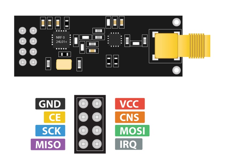
- GND (Ground): Used to connect the module to the ground of the power supply.
- VCC (Power Supply): Connects to the 3.3V power supply.
- CE (Chip Enable): Controls the module's power mode.
- CSN (Chip Select Not): Used to select the module for communication.
- SCK (Serial Clock): Used to synchronize the data transfer between the module and the microcontroller.
- MOSI (Master Out Slave In): Used to transfer data from the microcontroller to the module.
- MISO (Master In Slave Out): Used to transfer data from the module to the microcontroller.
- IRQ (Interrupt Request): Used to request an interrupt from the module.
Applications:
- Wireless data transfer: The module can be used for wireless data transfer between microcontrollers, computers, and other devices.
- Remote control systems: The module can be used to create remote control systems for controlling devices such as robots, lights, and appliances.
- Internet of Things (IoT) devices: The module can be used to create IoT devices such as smart home devices, sensors, and actuators.
- Wireless game controllers: The module can be used to create wireless game controllers for video games.
- Wireless audio systems: The module can be used to create wireless audio systems for transmitting audio signals between devices.
- Wireless data logging: The module can be used to log data wirelessly from sensors and other devices.
- Wireless monitoring and control systems: The module can be used to create wireless monitoring and control systems for industrial, agricultural, and other applications.
Circuit:
you will need two modules and two Arduino Uno and connect both as you see in the diagram:
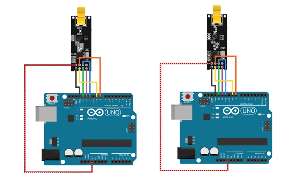
- Connect the GND pin on the NRF24L01+ module to a GND pin on the Arduino UNO.
- Connect the VCC pin on the NRF24L01+ module to a 3.3V pin on the Arduino UNO.
- Connect the CE pin on the NRF24L01+ module to digital pin 9 on the Arduino UNO.
- Connect the CSN pin on the NRF24L01+ module to digital pin 8 on the Arduino UNO.
- Connect the SCK pin on the NRF24L01+ module to digital pin 13 on the Arduino UNO.
- Connect the MOSI pin on the NRF24L01+ module to digital pin 11 on the Arduino UNO.
- Connect the MISO pin on the NRF24L01+ module to digital pin 12 on the Arduino UNO.
- Connect the IRQ pin on the NRF24L01+ module to digital pin 2 on the Arduino UNO.
This wiring diagram assumes that you will be using the SPI communication protocol to communicate between the NRF24L01+ module and the Arduino UNO.
Library:
- Open the Arduino IDE software on your computer.
- Go to the Sketch menu, select Include Library, and then Manage Libraries.
- In the search bar, type "RF24" and press enter.
- Locate the RF24 library by TMRh20 and click the Install button.
- Wait for the library to be installed and then close the Library Manager.
- To verify the installation, go to the Sketch menu, select Include Library, and look for the RF24 library. If it is listed, then the installation was successful.
Code:
Here is an example code for sending data from one Arduino UNO to another using the NRF24L01+ Wireless Transceiver Module with CE on digital pin 9 and CSN on digital pin 8:
#include "SPI.h"
#include "nRF24L01.h"
#include "RF24.h"
RF24 radio(9, 8);
const byte address[6] = "00001";
void setup() {
 Serial.begin(9600);
 radio.begin();
 radio.openWritingPipe(address);
 radio.setPALevel(RF24_PA_LOW);
}
void loop() {
 if (Serial.available()) {
 String input = Serial.readString();
 radio.write(&input[0], input.length());
 }
}
Here is an example code for receiving data from the other Arduino UNO and printing it on the serial monitor:
#include "SPI.h"
#include "nRF24L01.h"
#include "RF24.h"
RF24 radio(9, 8);
const byte address[6] = "00001";
char message[32];
void setup() {
 Serial.begin(9600);
 radio.begin();
 radio.openReadingPipe(0, address);
 radio.startListening();
}
void loop() {
 if (radio.available()) {
 radio.read(&message, sizeof(message));
 Serial.println(message);
 }
}
Technical Details:
- Frequency band: 2.4GHz ISM (Industrial, Scientific, and Medical) band
- Data rate: 1Mbps, 2Mbps
- Output power: -18dBm, -12dBm, -6dBm, and 0dBm (configurable)
- Reception sensitivity: -92dBm (1Mbps), -91dBm (2Mbps)
- Operating voltage: 1.9V to 3.6V
- Operating current: 11.3mA (transmitting), 12.5mA (receiving), 29uA (standby)
- Antenna: External SMA Antenna
- Range: up to 100 meters (indoors) and up to 1000 meters (outdoors with line-of-sight)
- Interface: SPI (Serial Peripheral Interface)
Resources:
Comparisons:
The normal NRF24L01 module has an onboard ceramic antenna, while the NRF24L01+ module has an SMA (SubMiniature version A) antenna connector, which allows for the use of external antennas.
Advantages of the NRF24L01+ with SMA antenna:
- Increased range: The use of an external antenna can increase the transmission range of the module, especially in challenging environments where the signal may be degraded or obstructed.
- Flexibility: External antennas come in different shapes and sizes and can be optimized for specific applications. This allows for greater flexibility in selecting the best antenna for the specific needs of the project.
- Improved performance: An external antenna can improve the overall performance of the module, including increased sensitivity, output power, and signal quality.
Disadvantages of the NRF24L01+ with SMA antenna:
- Complexity: The use of an external antenna can increase the complexity of the project, as the antenna must be properly connected and configured.
- Cost: External antennas can be more expensive than onboard ceramic antennas.
In general, the use of an external antenna with the NRF24L01+ can significantly increase the transmission range of the module, which may be necessary for certain applications. However, it may also increase the complexity and cost of the project. The choice between the two modules will depend on the specific needs and requirements of the project.