AED 9.45
Description
The KY-020 tilt switch sensor, also known as a ball switch sensor, is an electronic device that measures the orientation of an item and outputs a high or low signal. When this switch is tipped in the proper direction, the ball inside the sensor makes contact with a set of contacts, completing an electrical circuit.
Package Includes:
- 1 x KY-020 tilt switch sensor
Features:
- This kind of switch is safer than mercury switches and has the same characteristics.
- The trigger switch for low current circuit does not apply when the power switch
- The sensor is easy to interface with microcontrollers.
- Cheap and reliable
- It has a great durability rate.
Description:
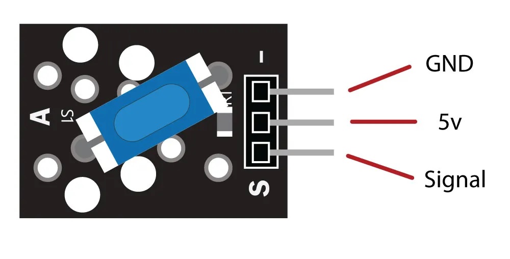
The Keyes KY-020 tilt switch includes a blue chamber inside which a little metal ball travels back and forth. The ball causes two electrical connections inside the chamber to open or close depending on the direction of the sensor. Tilt sensors are often used on 4X4 trucks and boats to warn the driver if the vehicle is about to roll over or capsize. The signal pin is denoted by the letter S. The Vcc pin is located in the center. The ground pin is indicated by the minus symbol (-).
Principle of Work:
Tilt sensors are composed of a plastic or glass tube with two wires and a metal ball within. When the tube is tilted forward, the ball rolls forward and only comes into contact with one wire. The ball rolls back and contacts both wires when the tube is turned backward. Current can now travel between the two wires. The Arduino can detect this high or low signal to determine whether or not the sensor is tilted.

Pinout of the Module:
| Pin Name | Description |
|---|---|
| (-) | GND or Ground |
| middle | Vcc which can be connected to 5 or 303v |
| S | Output of the module which is digital Hiigh or Low |
Applications:
- Robotics makes extensive use of it.
- It can also be applied to automobiles.
- to determine the direction.
- to be aware of the desire.
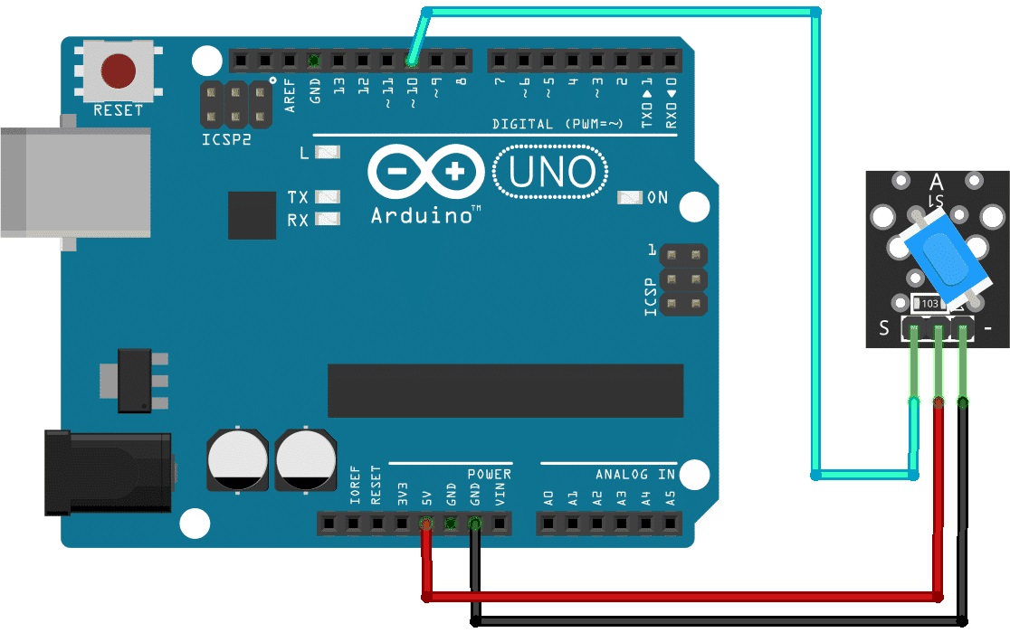
Circuit:
Assemble the Tilt Sensor using the Arduino UNO by connecting an LED to pin 13 with a 220ohm resistor or leave the onboard LED to light up and connect the sensor to pin 10. Now, copy and paste the code into your Arduino IDE. The code is then uploaded to Arduino. To see the glowing LED, tilt and move the sensor.
Library:
No Library is needed for this module to function
Code:
The input sensor pin and output LED pin that are connected to the Arduino pins has been defined. Then, by declaring the variable LastTiltState, we have shown that the sensor's previous stage was high. Next, we must specify the variables debounceDelay and lastdebounce time.
We have specified the sensor pin as the Arduino's input in the void setup. Led is also an output. Additionally, we initialized the serial monitor there.
We have defined the function digitalRead() in the void loop to examine the sensor reading. The sensor will reset the debouncing time if it detects a value identical to the previous lastTiltState stated above, as long as the requirement is met.
additionally returns the millisecond's value. The condition has been created since then. The lastTiltState becomes the sensorValue if the condition is verified. The lastTiltState is also taken by the LED pin. To display the sensor value on the serial monitor, use the Serial. println command.
int ledPin = 13;
int sensorPin = 10;
int sensorValue;
int lastTiltState = HIGH; // the previous reading from the tilt sensor
// the following variables are long's because the time, measured in miliseconds,
// will quickly become a bigger number than can be stored in an int.
long lastDebounceTime = 0; // the last time the output pin was toggled
long debounceDelay = 50; // the debounce time; increase if the output flickers
void setup(){
 pinMode(sensorPin, INPUT);
 digitalWrite(sensorPin, HIGH);
 pinMode(ledPin, OUTPUT);
 Serial.begin(9600);
}
void loop(){
 sensorValue = digitalRead(sensorPin);
 // If the switch changed, due to noise or pressing:
 if (sensorValue == lastTiltState) {
 // reset the debouncing timer
 lastDebounceTime = millis();
 }
 if ((millis() - lastDebounceTime) > debounceDelay) {
 // whatever the reading is at, it's been there for longer
 // than the debounce delay, so take it as the actual current state:
 lastTiltState = sensorValue;
 }
 digitalWrite(ledPin, lastTiltState);
 Serial.println(sensorValue);
 delay(500);
}
Technical Details:
- ON at 30-90 degrees from a horizontal position
- Max Current: 30mA
- voltage: 5v
- Insulation Resistance:>10M ohm
- 19 x 15 x 5 mm
Resources:
Comparisons: