Out Of Stock
Description
The Motor Driver Module 2Ch 1.2A 15V TB6612FNG is an electronic device that controls the speed and direction of two DC motors simultaneously. It uses the TB6612FNG motor driver IC to provide a maximum current of 1.2A per channel and supports a voltage range of up to 15V. This module is commonly used in robotics, automation, and other projects requiring precise motor control. It can be easily controlled through a microcontroller or single-board computer and features adjustable speed and acceleration settings.
Package Includes:
- 1 x TB6612FNG Motor Driver Module 2Ch 1.2A 15V
Features:
- Compact and easy-to-use motor driver module that can control two motors independently.
- It has a Maximum motor voltage of 15V and a maximum motor current of 1.2A per channel.
- Uses the TB6612FNG chip as the motor driver, which is a high-efficiency dual-channel motor driver IC.
- Built-in thermal shutdown circuit to prevent the module from overheating.
- Controlled using PWM signals for speed control and direction control signals for motor rotation.
- It has a Standby pin that can be used to turn off the motor outputs and reduce power consumption when the motors are not in use.
- Screw terminals for easy and secure connections to the power supply and motors.
- Compatible with a variety of microcontrollers and development boards such as Arduino and Raspberry Pi.
Description:
The Motor Driver Module 2Ch 1.2A 15V TB6612FNG is a compact and versatile electronic module that provides precise control of two DC motors. It features pin headers for easy connection to a microcontroller or single-board computer, making it suitable for various applications, including robotics, automation, and other projects that require precise motor control. The module uses the TB6612FNG motor driver IC, which can provide a maximum current of 1.2A per channel and supports a voltage range of up to 15V. It features six input pins: two PWM inputs for controlling the speed of each motor, two direction inputs for controlling the direction of each motor, and two enable inputs for enabling or disabling each motor. This motor driver module is easy to use and can be controlled through a microcontroller or single-board computer, such as an Arduino or Raspberry Pi. It also features adjustable speed and acceleration settings, allowing for precise control over the motion of the motors. The Motor Driver Module 2Ch 1.2A 15V TB6612FNG has a compact form factor, making it easy to integrate into various projects. It is also designed to provide reliable and efficient motor control, with built-in protection features such as overcurrent protection and thermal shutdown.
Principle of Work:
The Motor Driver Module 2Ch 1.2A 15V TB6612FNG works based on the H-bridge circuit configuration, which enables control of the direction and speed of DC motors. The module uses the TB6612FNG motor driver IC, which is a dual-channel H-bridge driver. The H-bridge is a configuration of four transistors that allows the motor to be driven in either direction by reversing the polarity of the applied voltage. To control the direction and speed of the motor, the module receives input signals from a microcontroller or single-board computer. The input signals include two PWM signals that control the speed of each motor, two direction signals that control the direction of each motor, and two enable signals that enable or disable each motor. When a PWM signal is applied to the motor driver module, the TB6612FNG IC regulates the voltage and current supplied to the motor to control its speed. Similarly, when a direction signal is applied, the module controls the polarity of the voltage supplied to the motor, allowing it to move in either direction. The enable signal allows the module to turn the motor on or off, conserving power when the motor is not in use. The TB6612FNG IC also includes built-in protection features such as overcurrent protection and thermal shutdown, which ensure the safe and efficient operation of the module and the motor. Overall, the Motor Driver Module 2Ch 1.2A 15V TB6612FNG provides precise control of two DC motors and is a reliable and efficient solution for various robotics, automation, and other projects that require precise motor control.
Pinout of the Module:
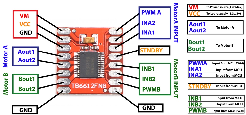
- VM: Motor voltage pin. This is where you connect the power supply for your motors.
- VCC: Module power supply pin. This is where you connect the power supply for the motor driver module itself.
- GND: Ground pin. Three ground pins on this module are all connected.
- A1: Motor A connection positive pin.
- A2: Motor A connection negative pin.
- B1: Motor B connection positive pin.
- B2: Motor B connection negative pin.
- PWMA: PWM pin for Motor A. This pin is used for the speed control of Motor A.
- PWMB: PWM pin for Motor B. This pin is used for the speed control of Motor B.
- AIN1: Control signal pin for Motor A.
- AIN2: Control signal pin for Motor A.
- BIN1: Control signal pin for Motor B.
- BIN2: Control signal pin for Motor B.
- STBY: Standby pin. This pin must be set to HIGH to activate the motor driver module.
Applications:
- Power monitoring: The module can be used to monitor the voltage level of an AC power supply and detect any fluctuations or interruptions in the power supply.
- Home automation: The module can be used in home automation systems to monitor the voltage level of AC appliances and control their operation based on the measured voltage level.
- Industrial control systems: The module can be used in industrial control systems to monitor the voltage level of machinery and equipment and control their operation based on the measured voltage level.
- Voltage regulators: The module can be used in the design of voltage regulators to control the output voltage level based on the measured input voltage level.
- Power supplies: The module can be used in the design of power supplies to monitor the input voltage level and protect the power supply from damage due to overvoltage or Undervoltage conditions.
Circuit:
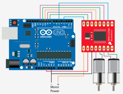
- Motor A is connected between A01 and A02
- Motor B is connected between B01 and B02
- STBY (pin 10): Standby pin for enabling/disabling the module
- PWMA (pin 3): Speed control pin for motor A
- AIN1 (pin 9): Control signal for motor A
- AIN2 (pin 8): Control signal for motor A
- PWMB (pin 5): Speed control pin for motor B
- BIN1 (pin 11): Control signal for motor B
- BIN2 (pin 12): Control signal for motor B
- VCC 5v from external source o more voltage depending on the motors
- GND should be common with the Arduino GND and the source GND
Library:
No library Needed
Code:
The code controls two motors (Motor A and Motor B) using an H-bridge motor driver connected to the Arduino:
const int STBY = 10; //standby pin

//Motor A
const int PWMA = 3; //Speed control pin
const int AIN1 = 9; //Direction pin
const int AIN2 = 8; //Direction pin

//Motor B
const int PWMB = 5; //Speed control pin
const int BIN1 = 11; //Direction pin
const int BIN2 = 12; //Direction pin

void setup() {
  pinMode(STBY, OUTPUT);

  pinMode(PWMA, OUTPUT);
  pinMode(AIN1, OUTPUT);
  pinMode(AIN2, OUTPUT);

  pinMode(PWMB, OUTPUT);
  pinMode(BIN1, OUTPUT);
  pinMode(BIN2, OUTPUT);

  stop(); //initially stop the motors
}

void loop() {
  move(PWMA, AIN1, AIN2, 255, 1); //motor A, full speed, left
  move(PWMB, BIN1, BIN2, 255, 1); //motor B, full speed, left

  delay(1000); //go for 1 second
  stop(); //stop
  delay(250); //hold for 250ms until move again

  move(PWMA, AIN1, AIN2, 128, 0); //motor A, half speed, right
  move(PWMB, BIN1, BIN2, 128, 0); //motor B, half speed, right

  delay(1000);
  stop();
  delay(250);
}

void move(int speedPin, int inPin1, int inPin2, int speed, int direction) {
  //Move specific motor at speed and direction
  //speedPin: pin for speed control
  //inPin1: pin for direction control
  //inPin2: pin for direction control
  //speed: 0 is off, and 255 is full speed
  //direction: 0 clockwise, 1 counter-clockwise

  digitalWrite(STBY, HIGH); //disable standby

  boolean inPinA = LOW;
  boolean inPinB = HIGH;

  if(direction == 1) {
    inPinA = HIGH;
    inPinB = LOW;
  }

  digitalWrite(inPin1, inPinA);
  digitalWrite(inPin2, inPinB);
  analogWrite(speedPin, speed);
}

void stop() {
  //enable standby
  digitalWrite(STBY, LOW);
}
- In the
setup()function, the code sets all the pins as output pins. - In the
loop()function, the code calls themove()function twice to move each motor. The first call tomove()sets both motors to full speed and move them to the left. After one second, thestop()function is called to stop the motors, and then the code waits for 250 milliseconds. The second callmove()sets both motors to half speed and moves them to the right. After another second, thestop()function is called to stop the motors, and the code waits for 250 milliseconds again. - The
move()function takes three arguments:motor,speed, anddirection. Themotorthe argument specifies which motor to move (Motor A or Motor B). Thespeedargument sets the speed of the motor (0 to 255, with 0 being off and 255 being full speed). Thedirectionargument sets the direction of the motor (0 for clockwise and 1 for counter-clockwise). The function sets theSTBYpin to high to enable the motor driver and then sets theAIN1,AIN2,BIN1, orBIN2pins depending on which motor is being moved and the direction. Finally, the function sets thePWMAorPWMBpin to the specified speed usinganalogWrite(). - The
stop()function simply sets theSTBYpin to low to disable the motor driver, which stops both motors.
Technical Specifications:
- Power supply voltage: VM=15V max, VCC=2.7-5.5V
- Output current: Iout=1.2A(average) / 3.2A (peak)
- Standby control to save power
- CW/CCW/short brake/stop motor control modes
- Built-in thermal shutdown circuit and low voltage detecting circuit
- 0.1" spaced pins
- Filtering capacitors on both supply lines
- Dimensions: 0.8x0.8"
Resources:
Comparisons:
The DRV8833 and the TB6612FNG are both dual H-bridge motor driver modules that are commonly used in robotics and other applications that require motor control. However, there are some differences between the two modules:
- Voltage range: The DRV8833 is designed to work with lower voltage motors (up to 10.8 V) while the TB6612FNG can handle higher voltage motors (up to 15 V).
- Current capacity: The TB6612FNG has a higher current capacity than the DRV8833, making it better suited for driving larger motors.
- Control interface: Both modules use PWM signals to control the motor speed, but the TB6612FNG offers additional control modes such as "standby mode" and "sleep mode."
- Heat dissipation: The DRV8833 has a smaller package size and lower power consumption, resulting in less heat generation than the TB6612FNG.