AED 36.75
Description
WIFi ESP8266 WIFI D1 MINI Dev. Board, USB ch340G (32Mb flash) is an integrated ESP8266 based WiFi enabled microprocessor unit + 8/16/32Mb(megabit) flash memory.WIFi D1 mini board using the Ard. IDE.For connect to PC need install driver for ch340.On board have embedded WiFI antenna it uses the same pinout of ESP8266 WIFI D1 MINI wiring fo you can use all the tutorial of D1 MINI with it.
Documents
Dimensional drawing |  |  |
Pinout |  | |
Schematic | | |
to control the garage door using the phone. we can use an ESP8266 based D1 Mini and Home Assistant.
Here are the parts that will be needed:
D1 Mini
MicroUSB Cable and charger
5V Relay
Magnetic Reed Switch/Door Sensor
22 Gauge 2 Conductor Wire
Electronic Project Case (Optional)
Software Requirements:
- Home Assistant configured with an MQTT broker such as Mosquitto
- Arduino IDE
I’m going to assume that Home Assistant, MQTT, and Arduino IDE are all setup. There are plenty of guides out there on how to set those up. If anyone reading this does need help with any of that, feel free to post a comment.
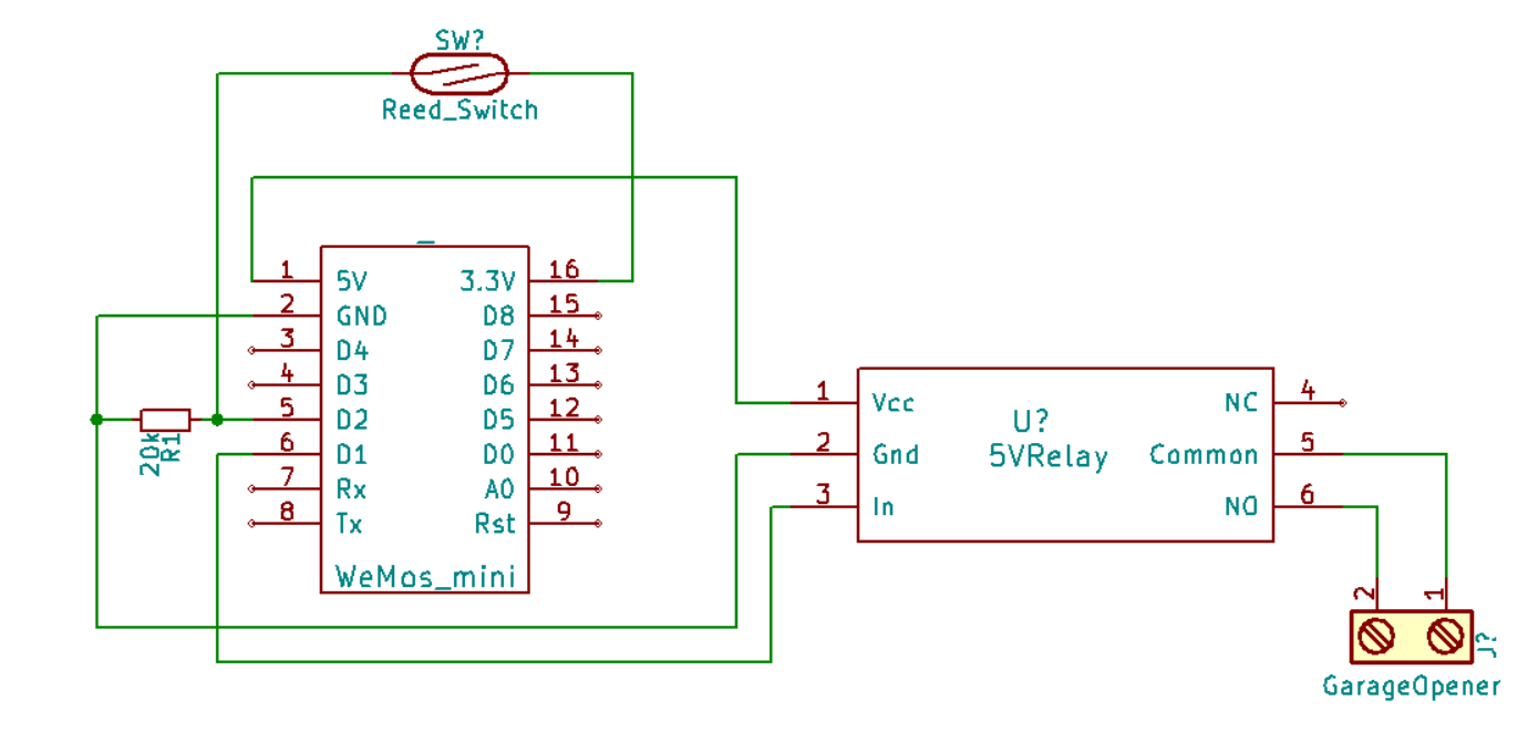
- The first thing we will need to do is wire up the d1. The schematic below shows how I wired mine. If for any reason, you don’t use the same pins as I did on the d1, keep in mind that the chip will send some pins to high on startup. That would trigger the Relay, and unexpectedly open your garage door. Be mindful of which pin you use.
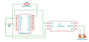
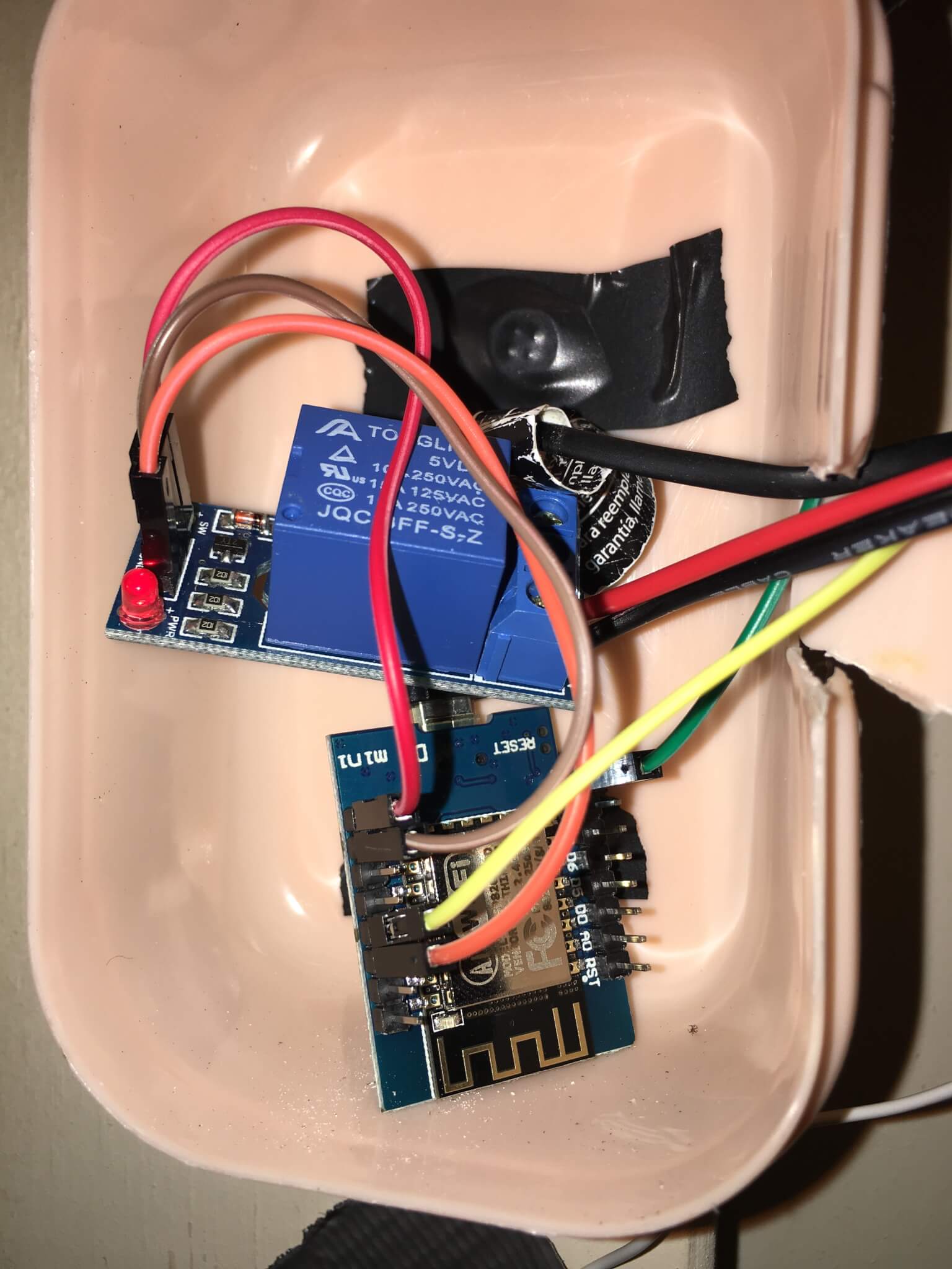
Garage Door Opener d1 Schematic 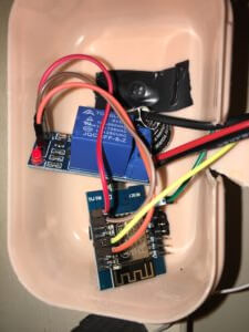
My d1 and Relay. - Next, we need to upload the code below to the d1. You will need to edit the custom parameters section as needed. The first time you upload the firmware, you will need to do it via serial using a USB cable. After the firmware is on there, you can do the updates Over-The-Air (OTA). The code below uses WifiManager, which starts the d1as an AP if it can’t connect to a Wifi network. You can then connect to the AP to setup Wifi on the d1 . The settings will be saved across reboots.
For OTA, in Arduino IDE, click Tools -> Flash Size -> 4M (1M SPIFFS). If you don’t do this, the firmware will not work on the d1 . Next, compile it in Arduino IDE using CTRL+ALT+S. That will compile a *.bin file in the same directory as your *.ino. You can use your web browser to go to http://
/WebFirmwareUpgrade and upload the *.bin file. It will then reboot in about 30 seconds with the new code.
- The first thing we will need to do is wire up the d1. The schematic below shows how I wired mine. If for any reason, you don’t use the same pins as I did on the d1, keep in mind that the chip will send some pins to high on startup. That would trigger the Relay, and unexpectedly open your garage door. Be mindful of which pin you use.
#include           //ESP8266 Core WiFi Library (you most likely already have this in your sketch)
#include             //Local DNS Server used for redirecting all requests to the configuration portal
#include      //Local WebServer used to serve the configuration portal
#include           //https://github.com/tzapu/WiFiManager WiFi Configuration Magic
#include          //MQTT
#include
#include

////**********START CUSTOM PARAMS******************//

//Define parameters for the http firmware update
const char* host = "GarageESP";
const char* update_path = "/WebFirmwareUpgrade";
const char* update_username = "admin";
const char* update_password = "YourPassWordHere";

//Define the pins
#define Relay_PIN 5
#define DOOR_PIN 4

//Define MQTT Params. If you don't need to
#define mqtt_server "MQTT Broker IP Address"
#define door_topic "garage/door"
#define button_topic "garage/button"
const char* mqtt_user = "mqtt_user";
const char* mqtt_pass = "mqtt_pass";

//************END CUSTOM PARAMS********************//
//This can be used to output the date the code was compiled
const char compile_date[] = __DATE__ " " __TIME__;

//Setup the web server for http OTA updates.
ESP8266WebServer httpServer(80);
ESP8266HTTPUpdateServer httpUpdater;

WiFiClient espClient;

//Initialize MQTT
PubSubClient client(espClient);

//Setup Variables
String switch1;
String strTopic;
String strPayload;
char* door_state = "UNDEFINED";
char* last_state = "";

//Wifi Manager will try to connect to the saved AP. If that fails, it will start up as an AP
//which you can connect to and setup the wifi
WiFiManager wifiManager;
long lastMsg = 0;

void setup() {
  //Set Relay(output) and Door(input) pins
  pinMode(Relay_PIN, OUTPUT);
  pinMode(Relay_PIN, LOW);
  pinMode(DOOR_PIN, INPUT);

  Serial.begin(115200);

  //Set the wifi config portal to only show for 3 minutes, then continue.
  wifiManager.setConfigPortalTimeout(180);
  wifiManager.autoConnect(host);

  //sets up the mqtt server, and sets callback() as the function that gets called
  //when a subscribed topic has data
  client.setServer(mqtt_server, 1883);
  client.setCallback(callback); //callback is the function that gets called for a topic sub

  //setup http firmware update page.
  MDNS.begin(host);
  httpUpdater.setup(&httpServer, update_path, update_username, update_password);
  httpServer.begin();
  MDNS.addService("http", "tcp", 80);
  Serial.printf("HTTPUpdateServer ready! Open http://%s.local%s in your browser and login with username '%s' and your password\n", host, update_path, update_username);
}

void loop() {
  //If MQTT client can't connect to broker, then reconnect
  if (!client.connected()) {
    reconnect();
  }
  checkDoorState();
  client.loop(); //the mqtt function that processes MQTT messages
  httpServer.handleClient(); //handles requests for the firmware update page
}

void callback(char* topic, byte* payload, unsigned int length) {
  //if the 'garage/button' topic has a payload "OPEN", then 'click' the Relay
  payload[length] = '\0';
  strTopic = String((char*)topic);
  if (strTopic == button_topic)
  {
    switch1 = String((char*)payload);
    if (switch1 == "OPEN")
    {
      //'click' the Relay
      Serial.println("ON");
      pinMode(Relay_PIN, HIGH);
      delay(600);
      pinMode(Relay_PIN, LOW);
    }
  }
}

void checkDoorState() {
  //checks if the door state has changed, and MQTT pub the change
  last_state = door_state; //get previous state of door
  if (digitalRead(DOOR_PIN) == 0) // get new state of door
    door_state = "OPENED";
  else if (digitalRead(DOOR_PIN) == 1)
    door_state = "CLOSED";

  if (last_state != door_state) { // if the state has changed then publish the change
    client.publish(door_topic, door_state);
    Serial.println(door_state);
  }
  //pub every minute, regardless of a change.
  long now = millis();
  if (now - lastMsg > 60000) {
    lastMsg = now;
    client.publish(door_topic, door_state);
  }
}

void reconnect() {
  //Reconnect to Wifi and to MQTT. If Wifi is already connected, then autoconnect doesn't do anything.
  wifiManager.autoConnect(host);
  Serial.print("Attempting MQTT connection...");
  if (client.connect(host, mqtt_user, mqtt_pass)) {
    Serial.println("connected");
    client.subscribe("garage/#");
  } else {
    Serial.print("failed, rc=");
    Serial.print(client.state());
    Serial.println(" try again in 5 seconds");
    // Wait 5 seconds before retrying
    delay(5000);
  }
}
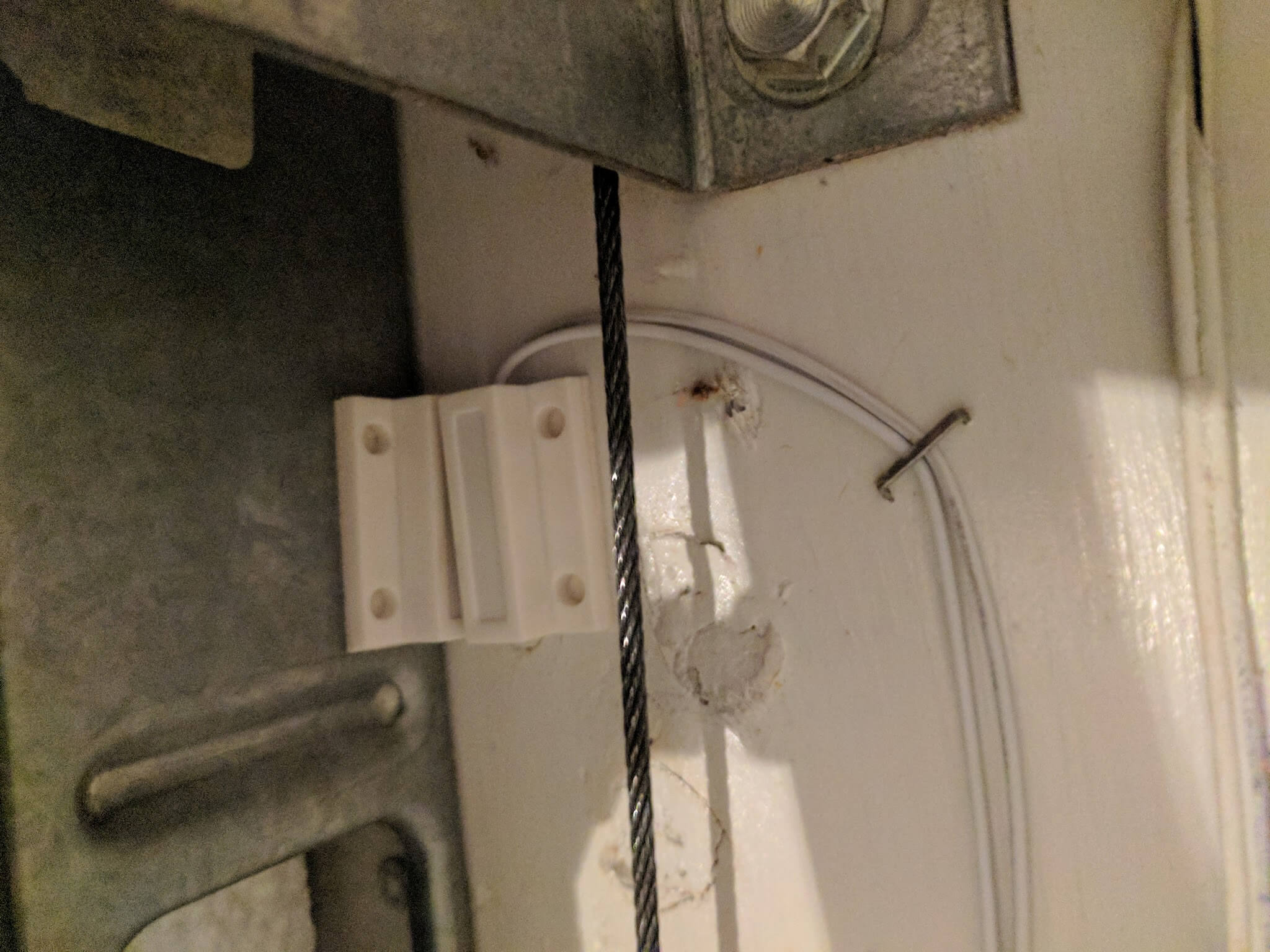
- Now to connect it to the garage door opener. The wired piece
- of the reed switch will go onto the wall, right next to the garage door. The other part of the reed switch will go on the door itself. You want to be very careful here to make sure that piece is in a place where it won’t get knocked off by something when the garage door moves up.
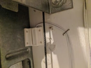
The reed switch (The wired piece) has to be within about 1/4″ from the magnetic piece when the door is closed. 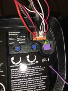
Note the red wire in the first terminal, and the black wire on the second terminal. These are going into Common and NC on the Relay. On the garage door opener itself, you need to find the terminals where the wires for the wall button are located. You will most likely have 4 or more terminals. Two of those terminals are for the wall button. If you can’t figure out which ones they are, then you can try just taking a wire and shorting 2 terminals at a time until the door opens. Or you can disconnect one wire at a time until the button stops working.Once you have found those 2 terminals, connect a wire to each one. The other end of one of the wires(it doesn’t matter which one) goes to the Common terminal on the Relay. The other wire connects to the NO (normally open) terminal. Now you can put it in the case and power it up.
- The last thing that is left to do is configure Home Assistant. To do that, simply add in the following code into your *.yaml file. This configuration sends the appropriate payload via MQTT to open/close the door, and looks for the payload based on the sensor to determine if the door is closed or not:
cover:
  - platform: mqtt
    name: Garage Door
    friendly_name: Garage
    state_topic: "garage/door"
    command_topic: "garage/button"
    payload_open: "OPEN"
    payload_close: "OPEN"
    payload_stop: "OPEN"
    state_open: "OPENED"
    state_closed: "CLOSED"
    optimistic: false
    retain: false
    value_template: '{{ value }}'
The garage door should show up in Home Assistant as a Cover. You can tell the state of the door based on which arrow is grayed out.