Out Of Stock
Description
This is an 8-channel relay board from RobotDyn can be controlled directly by any MCUs like Arduino, AVR, PIC, ARM, PLC, and others. This relay module has a 5V active high voltage. optical isolators are built into the module. This solution saves your microcontroller from a high voltage for VAC/VDC
Package Includes:
- 1 x Relay Module from RobotDyn 8 channel Relay, 5V
Features:
- Each relay features an LED indicator
- Color: Black
- Optocoupler included on the board for reducing the distortion.
- One normally closed contact and one normally open contact
- High-impedance controller pin
- Power supply indicator and Control indicator lamp
- The power source can be configured with a jumper located on the board.
Description:
This is an 8-channel relay interface board that can be controlled directly by a variety of microcontrollers including Arduino, AVR, PIC, ARM, PLC, and others. Capable of controlling various appliances and other high-current equipment This relay module has a 5V active high voltage. The optocoupler, also known as an optocoupler, photocoupler, or optical isolator, is built into the 8-channel Relay module. An optocoupler is a component that uses light to transfer electrical signals between two states of isolation circuits while keeping high voltage from affecting the system receiving the signal. The maximum contact of the relay is AC250V 10A and DC30V 10A. Microcontrollers can be directly connected to the standard interface. Red working status indicator lights give safety features. All MCU control, industrial sector, PLC control, and smart home control are widely used.
Principle of Work:
A relay is a type of switch that can be controlled with an electrical signal. It is a way to open or close a circuit in this case via a signal from the connected microcontroller. The relay isolates the circuit on the device you want to control from the device that's controlling it. and High-level triggered will allow the current to go through the power line when the control signal is High. optocoupler on the other hand makes real photo isolation between the relay and the MCU which is very good to minimize the distortion from the other side
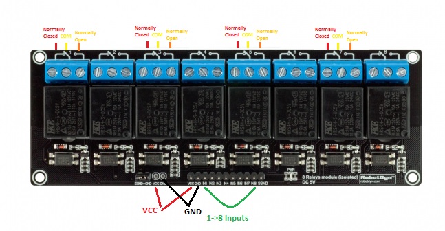
Pinout of the Module:
Applications:
- Relay Drive from External Contacts.
- LED Series and Parallel Connections.
- Electronic Circuit Drive by Means of a Relay.
- Home automation
- Battery backup
- High current load switching
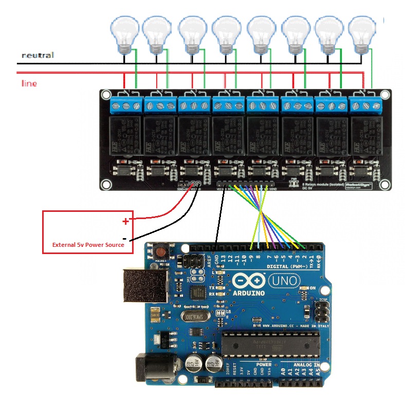
Circuit:
in this example, we will blink an 8 220v lamp for 1sec and shut it down for 1sec.
Library:
This Module doesn't need a library to work.
Code:
void setup() {
  pinMode(2, OUTPUT);
 pinMode(3, OUTPUT);
 pinMode(4, OUTPUT);
 pinMode(5, OUTPUT);
 pinMode(6, OUTPUT);
 pinMode(7, OUTPUT);
 pinMode(8, OUTPUT);
 pinMode(9, OUTPUT);
}

// the loop function runs over and over again forever
void loop() {
 digitalWrite(2,HIGH); delay(1000);
 digitalWrite(3,HIGH); delay(1000);
 digitalWrite(4,HIGH); delay(1000);
 digitalWrite(5,HIGH); delay(1000);
 digitalWrite(6,HIGH); delay(1000);
 digitalWrite(7,HIGH); delay(1000);
 digitalWrite(8,HIGH); delay(1000);
 digitalWrite(9,HIGH); delay(1000);
  digitalWrite(2,LOW);  delay(1000);
 digitalWrite(3,LOW); delay(1000);
 digitalWrite(4,LOW); delay(1000);
 digitalWrite(5,LOW); delay(1000);
 digitalWrite(6,LOW); delay(1000);
 digitalWrite(7,LOW); delay(1000);
 digitalWrite(8,LOW); delay(1000);
 digitalWrite(9,LOW); delay(1000);
}
Technical Details:
- 8 Channel
- Maximum switching voltage: 250VAC / 30VDC
- Maximum switching current: 10A
- Module operating voltage: 5V
Resources:
Comparisons:
This is a 5v Relay Board with an optocoupler which is very useful this device lowers the distortion from the power lines and makes the circuit more isolated and better than the boards where no such a device is included so you always need to connect the GND of the MCU GND of the circuit which is not very good idea sometimes this functionality can be also implemented in the SSR devices and if we want to compare this relay board to the SSR This kind of relay board has so many advantages like being able to withstand large inrush currents and high mechanical structure reliability, not being susceptible to the external electromagnetic environment, and being able to carry high voltage, and high current load but still, it has multiple disadvantages to the SSR Boards that they are slower than SSRs at 5 to 15ms and it has a larger package size, are not suitable for small projects and electromechanical relays tend to have a shorter life than other types of relays due to mechanical wear if you interested in SSRs you can get it from here