AED 19.95
Description
The LR7843 N-Channel logic compatible MOSFET with ultra-low Rds(on) which this MOSFET module is Based on for moderate to higher current low-side switching applications of up to 15A continuous. Excellent as a PWM Motor Driver Unit
Package Includes:
- LR7843 MOSFET Control Module
- 3-pin Screw Terminal
- 2-pin Screw Terminal
- The small male header strip
Features:
- These modules' designs include an optocoupler on the input, which biases the input from the output load voltage and is independent of the logic levels used for the drive signal. A 3.3V input, for example, will drive the same amount of current as a 5V input.
-
The modules use the LR7843 N-channel MOSFET, which has a typical Rds(on) resistance of 3.3m.
- With a load voltage of 12V, these modules can support approximately 15A of continuous current. When driven by PWM, the maximum peak current can reach 30A or higher.
- It should be noted that to avoid potential damage when using the module with inductive loads, an external fly-back diode should be used.
Description:
The LR7843 N-Channel logic compatible MOSFET with extremely low Rds(on) is used in this MOSFET module with optoisolation for low-side switching applications requiring moderate to high currents of up to 15A continuously. The circuit has an optocoupler on the input that separates the input from the output load voltage and is unaffected by the logic levels applied to the driving signal. For instance, a 3.3V input can generate the same amount of current as a 5V input. This little module can take a surprising amount of power considering its size. It works well for basic ON/OFF operations like controlling a solenoid or PWM control like dimming an array of LEDs. Additionally, these modules may be connected in parallel to boost the power handling capacity.
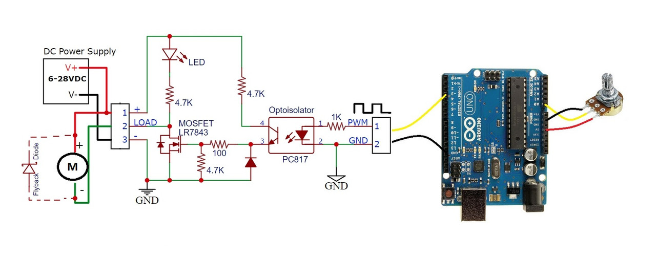
Principle of Work:
A PC817 optoisolator is included in the module to provide electrical isolation between the high-powered MOSFET side and the logic signals used to control the module. If something goes wrong and the MOSFET burns out, it should not harm the MCU that is controlling it. The module's MCU PWM input drives the internal LED side of the optoisolator. This input contains a 1K ohm series current limiting resistor to keep the current through the LED at safe levels, allowing the input to be driven by up to a 20V input or even higher if an MCU is not used. The internal LED in the optoisolator turns off when the PWM input signal is weak or disconnected, which in turn keeps the phototransistor output off. A 4.7K resistor pulls the MOSFET's gate to the ground while the phototransistor is off. As a result, the load is cut off from the ground and the MOSFET remains off. The internal optoisolator LED is turned on by a logic high on the PWM input, which then activates the phototransistor. By doing this, a voltage divider made mostly of two 4.7K resistors is produced. This turns on the MOSFET by biassing the gate to 50% of the power supply voltage. The gate will operate at 6V when a 12V power source is applied. The power supply is restricted to a minimum of roughly 6V because of the MOSFET's maximum gate voltage, which is 50% of the power supply voltage, is required to switch it on. If trying to draw more than a few amps through the module, a minimum power supply of 9V is advised because power dissipation in the MOSFET will be higher at lower power supply voltages. The load is wired to the ground to complete the circuit and receive power when the MOSFET conducts. Additionally, it serves as a ground for the onboard LED, which illuminates when the MOSFET is turned on. The onboard LED's current is restricted to acceptable levels over the 6-36V operating range by a 4.7K resistor.
Pinout of the Module:
Three connections are needed for the module. A DC power source to power the device (load) being controlled; a logic signal to switch the MOSFET on or off; and finally, the load itself. There are provided solderable connectors, however, if direct wiring is preferred, these connections can easily be constructed.
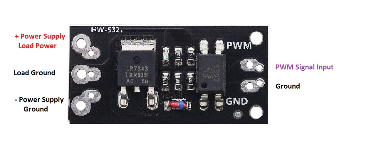
Driving Signal Connections: Connections to the MCU are made using the 2-pin connector on the right side. It contains two holes on 0.1′′ centres that can also accommodate a conventional male header, which may be useful in a breadboard arrangement, and two holes on 4mm centres that support a two-position screw terminal. PWM stands for the signal and GND for the signal ground on the pins.
DC Load Power Supply: is attached to the three 3-pin screw terminals on the rear of the module that are designated +, LOAD, and -. The ground connection is connected to - and the positive lead of the power supply is connected to +. A load power supply of 6–28 VDC is supported by the module.
Load: The load which is being driven is connected to the screw terminals marked + and Load on the back of the module. The positive lead of the load connects to the + terminal and the negative lead of the load connects to the center load ground terminal.
The signal ground and the load ground connections are not connected together on the module due to the optoisolator being used to provide isolation between the MOSFET power circuit and the MCU.
Applications:
- LED Dimming
- Motor speed control
Circuit:
To get this circuit to work you will need a PWM source, you could use an Arduino with Pot and program one of the board PWM pins to act like a PWM source. with this set up you will be able to control a motor or LED strip with a voltage between 6 and 36v.
Library:
This Module doesn't need a library to work.
Code:
void setup() {
pinMode(3,1);
}

void loop() {
int a = analogRead(A0);
analogWrite(3,a/4);
delay(50);
}
Technical Details:
- Ultra-low 3.3mΩ Rds(on) resistance
- 2.5V – 20V input control voltage with optoisolation
- 6 – 28V output switching voltage
- 15A continuous current handling capability
- 3.3 and 5V logic compatible
Resources:
Comparisons:
These modules work well for basic ON/OFF operation such as for driving a solenoid or PWM control such as for dimming an array of LEDs and can handle a surprising amount of power given a small size. It is also possible to parallel these modules to further increase the power handling capability. Though the maximum current spec for the MOSFET is 50A, do not expect to run 50A through this small module as it will quickly overheat due to the minimal heatsink capability of the small PCB, the IRF520 module works exactly the same as this module but the only difference that it doesn't include an optocoupler that means there is no real isolation between the input and the output which might damage the MCU in some cases that is and advantage to our Item