AED 78.75
Low stock
1
Description
The DFRobot FireBeetle ESP8266 is a low-power development board designed for IoT applications. It features an integrated IoT WiFi, TCP/IP, 32-bit MCU, 10-bit ADC, and multiple interfaces including HSPI, UART, PWM, I2C, and I2S. It operates with minimal power consumption (1.2mW at DTIM10) and includes 16MB of external SPI flash memory for program and firmware storage. The FireBeetle ESP8266 is compatible with Arduino programming, simplifying development and enhancing stability.
Features
- Low power consumption IoT development board
- Integrated IoT WiFi and TCP/IP stack
- 32-bit MCU (Tensilica L106)
- 10-bit ADC
- Multiple interfaces: HSPI, UART, PWM, I2C, I2S
- 16MB external SPI flash memory
- Compatible with Arduino programming
- DTIM10 power consumption: 1.2mW
- Operating voltage: 3.3V
- Digital pins: 10
- Analog pins: 1
- Compatible with various development tools including RTOS and MicroPython
Specifications
- Operating Voltage: 3.3V
- Input Voltage (limits): 3.3~5V (Lithium Battery: 3.7V & USB: 5V)
- Microcontroller: Tensilica L106 (32-bit MCU)
- Clock Speed: 80MHz (Maximum: 160MHz)
- SRAM: 50KB
- External Flash Memory: 16MB
- DC Current in Low-Power-Consumption: 46µA
- Average Operating Current: 80mA
- Maximum Discharging Current: 600mA (LDO-3.3 Output)
- Maximum Charging Current: 500mA
- Digital Pin x10
- Analog Pin x1
- SPI interface x1
- I2C interface x1
- IR interface x1
- I2S interface x1
- Interface: XH2.54mm Pin (No soldering default)
- WiFi: IEEE802.11 b/g/n (2.4 GHz~2.5 GHz), not support 5GHz WiFi
- Operating Temperature: -10℃~+55℃
- Dimension: 58 × 29(mm)
- Weight: 24g
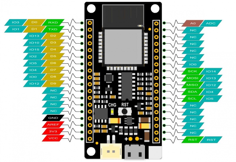
Pinout
- chG Blink: Not connected battery
- Light on: Charging
- Light off: Charge complete
Setup Instructions
-
Requirements:
- Hardware: FireBeetle ESP8266 IoT Microcontroller, Micro USB Cable
- Software: Arduino IDE (latest version)
- Drivers: cp40 Driver, CH340 Driver
-
Setup Arduino IDE:
- Plug FireBeetle into your computer, install the driver manually.
- Add FireBeetle Board URL to Arduino IDE:
- Open Arduino IDE, go to
File > Preferences. - Find
Additional Boards Manager URLsand paste the following link: - Click
OK. - Open
Tools > Board > Boards Manager, wait for the update, and findFireBeetle-ESP8266. ClickInstall.
- Open Arduino IDE, go to
Documents
Package Includes
- FireBeetle ESP8266 IoT Microcontroller x 1
- Micro USB Cable x1