AED 9.45
Description
The PCF8574 is an 8-bit I/O port expander that allows you to control up to 8 digital I/O ports through the I2C protocol, using only the SDA and SCL pins on your Arduino board. This 8-bit input/output (I/O) expander uses a two-line bidirectional bus (I2C) and can operate with VCC voltage ranging from 2.5 to 6 volts. It comes equipped with a latched output that has high-current drive capabilities, which is located on the device's 8-bit quasi-bidirectional I/O port (P0-P7). You can directly drive small loads, such as LEDs, with this feature. Additionally, each quasi-bidirectional I/O can be used as either an input or an output without requiring a data-direction control signal.
Package Includes:
- 1 x PCF8574 is an 8-bit I/O Port Expander Red
Features:
- Support cascading: You can use up to 8 PCF8574 modules to extend up to 64 digital I/O ports at the same time. This makes it possible to interface with a large number of sensors and devices using just a few microcontroller pins.
- Address configuration: The PCF8574 can be configured with a toggle switch to change its I2C address. This allows you to use multiple PCF8574 modules on the same I2C bus without addressing conflicts.
- Compact size: The PCB size of the PCF8574 is small, measuring just 36 x 16mm (1.41 x 0.62 inches). This makes it easy to integrate into your electronic projects.
- Output testing: The PCF8574 includes a testing feature that automatically toggles the P0-P7 ports every 2 seconds, outputting a high level and then a low level. If you set the three toggle switches to the ON position, the I2C address of the module will be set to 0x27.
- Voltage range: The PCF8574 is designed to operate with a voltage range of 2.5 to 6 volts, making it compatible with a wide range of microcontrollers and electronic devices.
Description:
The PCF8574 is an 8-bit I/O port expander integrated circuit (IC) designed to extend the digital I/O capabilities of microcontrollers such as Arduino. With the PCF8574, you can control up to 8 digital I/O ports through the I2C protocol, using only the SDA and SCL pins on your Arduino board. The I2C protocol is a two-wire serial communication protocol that allows multiple devices to be connected to the same bus, and it's widely used in many electronic devices. The PCF8574 uses this protocol to communicate with the microcontroller and expand its I/O capabilities. The PCF8574 is designed to operate with VCC voltage ranging from 2.5 to 6 volts, which makes it compatible with a wide range of microcontrollers and electronic devices. The device also features a latched output that has high-current drive capabilities. This output is located on the device's 8-bit quasi-bidirectional I/O port (P0-P7), which can be used to directly drive LEDs or other small loads. One of the great things about the PCF8574 is that each quasi-bidirectional I/O can be used as either an input or an output without requiring a data-direction control signal. This means that you can configure each I/O port as needed, making it easier to interface with different types of sensors and devices.
Principle of Work:
The PCF8574 module is an I/O expander that works by communicating with a microcontroller through the I2C protocol. The I2C protocol is a two-wire serial communication protocol that allows multiple devices to be connected to the same bus. The PCF8574 uses this protocol to communicate with the microcontroller and expand its digital I/O capabilities. The PCF8574 module has 8 I/O ports, labeled as P0 to P7, which can be used as either inputs or outputs. Each I/O port can be individually configured as an input or an output by writing to the corresponding bit in the PCF8574's control register. The PCF8574 also includes a latched output with high-current drive capabilities. This output is located on the device's 8-bit quasi-bidirectional I/O port (P0-P7), which can be used to directly drive LEDs or other small loads. One of the great features of the PCF8574 module is that it can be cascaded with other PCF8574 modules to expand the number of I/O ports. Each PCF8574 module has a unique I2C address, which can be set by a toggle switch on the module. By setting the I2C address of each module differently, you can connect up to 8 modules to the same I2C bus and control up to 64 digital I/O ports.
Multiple Addresses:
If you daisy-chain the modules, you will need to set a different address for each of the modules.
| Address (Hex) | A2 | A1 | A0 |
| 0x20 | LOW | LOW | LOW |
| 0x21 | LOW | LOW | HIGH |
| 0x22 | LOW | HIGH | LOW |
| 0x23 | LOW | HIGH | HIGH |
| 0x24 | HIGH | LOW | LOW |
| 0x25 | HIGH | LOW | HIGH |
| 0x26 | HIGH | HIGH | LOW |
| 0x27 | HIGH | HIGH | HIGH |
Pinout of the Module:
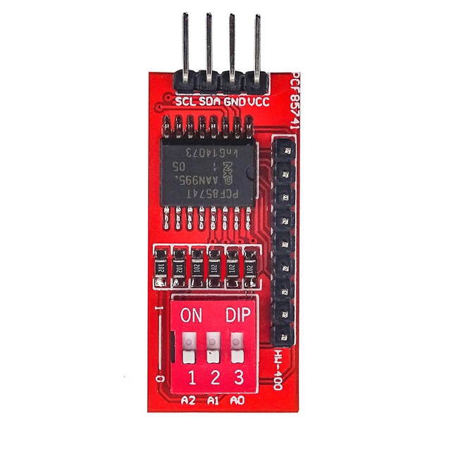
Pin 1: GND- Ground
Pin 2: VCC - Power supply voltage (2.5V to 6V)
Pin 3: SDA - Serial data input/output pin for I2C communication
Pin 4: SCL - Serial clock input pin for I2C communication
Pin 5-12: P0 to P7 - Bidirectional I/O ports that can be individually configured as inputs or outputs
Pin 13: A0 - Address bit 0, used to set the I2C address of the module
Pin 14: A1 - Address bit 1, used to set the I2C address of the module
Pin 15: A2 - Address bit 2, used to set the I2C address of the module
Applications:
- Driving LEDs and other small loads: The latched output with high-current drive capabilities of the PCF8574 module makes it ideal for driving LEDs and other small loads.
- Input/output expansion for microcontrollers: The PCF8574 module provides a simple and cost-effective way to expand the number of digital I/O ports available to a microcontroller.
- Sensor interfacing: The PCF8574 module can be used to interface with a variety of sensors that require digital I/O ports for communication.
- Home automation: The PCF8574 module can be used in home automation projects to control lights, appliances, and other devices.
- Robotics: The PCF8574 module can be used in robotics projects to control motors, servos, and other devices that require digital I/O control.
- Industrial automation: The PCF8574 module can be used in industrial automation projects to control sensors, actuators, and other devices.
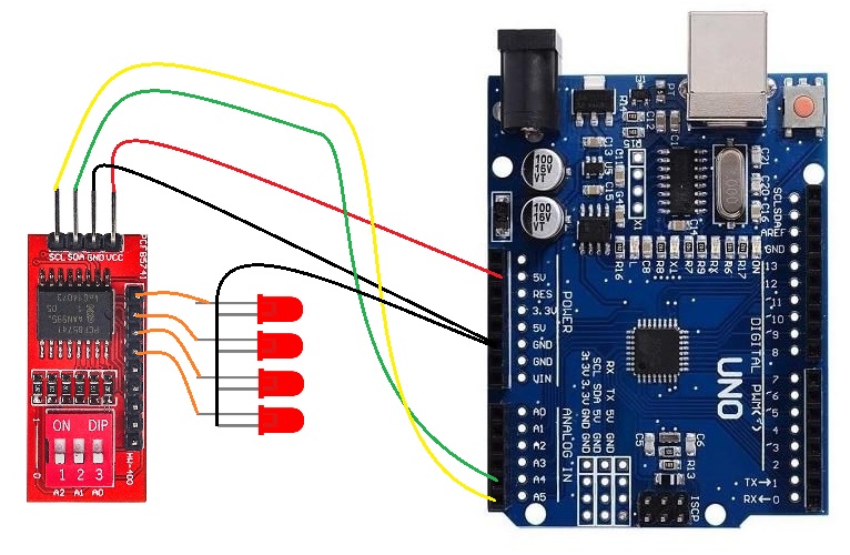
Circuit:
- Connect the VCC pin of the PCF8574 module to the 5V pin of the Arduino.
- Connect the GND pin of the PCF8574 module to the GND pin of the Arduino.
- Connect the SDA pin of the PCF8574 module to the SDA pin of the Arduino.
- Connect the SCL pin of the PCF8574 module to the SCL pin of the Arduino.
- Connect the LED one by one to the module outputs and the short legs to the GND.
Library:
To install the "PCF8574" library, follow these steps:
- Open the Arduino IDE on your computer.
- In the Arduino IDE, go to "Sketch" > "Include Library" > "Manage Libraries..."
- The Library Manager will open, displaying a list of available libraries.
- In the search bar at the top right corner of the Library Manager, type "PCF8574" by RobTillaart.
- The "PCF8574" library should appear in the list below. Click on it to select it.
- Click the "Install" button to install the library.
- Wait for the installation process to complete.
Code:
This code is an example of how to use the PCF8574 library to control the I/O ports of a PCF8574 module connected to an Arduino using the I2C protocol.
#include "PCF8574.h"

PCF8574 pcf8574(0x27); // Initialize the PCF8574 module with the I2C address

void setup() {
  pinMode(13, OUTPUT); // Set the built-in LED pin as an output
}

void loop() {
  pcf8574.write(0xFF); // Write all HIGH to the I/O ports (P0-P7)
  digitalWrite(13, HIGH); // Turn on the built-in LED
  delay(1000); // Delay for 1 second

  pcf8574.write(0x00); // Write all LOW to the I/O ports (P0-P7)
  digitalWrite(13, LOW); // Turn off the built-in LED
  delay(1000); // Delay for 1 second
}
- It initializes the PCF8574 module with the I2C address 0x27.
- In the
setup()function, it sets the built-in LED pin (pin 13) as an output. - In the
loop()function, it writes all HIGH to the I/O ports (P0-P7) of the PCF8574 module using thewrite()the function of the PCF8574 library. - It turns on the built-in LED by setting its pin to HIGH using the
digitalWrite()function. - It delays for 1 second using the
delay()function. - It writes all LOW to the I/O ports (P0-P7) of the PCF8574 module using the
write()the function of the PCF8574 library. - It turns off the built-in LED by setting its pin to LOW using the
digitalWrite()function. - It delays for 1 second using the
delay()function.
Technical Details:
- Operating voltage: 2.5V to 6V DC
- Number of I/O ports: 8 (P0-P7)
- I2C address: configurable via DIP switches (0x20 to 0x27)
- Current rating: up to 100mA per I/O port
- Operating temperature: -40°C to +85°C
- Communication protocol: I2C (Two-Wire Interface)
- Support for cascading up to 8 modules to extend up to 64 I/O ports
- Dimensions: 36mm x 16mm x 4mm (L x W x H)
Resources:
Comparisons:
Both the PCF8574 module and the 74HC595 shift register are frequently utilized to increase the number of digital I/O ports on an Arduino board. Here are some distinctions between the two:
- A number of I/O ports: The PCF8574 module has 8 I/O ports (P0-P7), while the 74HC595 shift register has 8 output ports (Q0-Q7) and 1 input port (DS). This means that the 74HC595 can be used to expand the number of output ports only, while the PCF8574 can be used to expand the number of input and output ports.
- Communication protocol: The PCF8574 module uses the I2C protocol for communication, while the 74HC595 uses the Serial Peripheral Interface (SPI) protocol. The I2C protocol requires fewer pins (only two: SDA and SCL) compared to SPI (four or more), which can simplify the wiring and reduce the number of pins required on the microcontroller.
- Speed: The 74HC595 shift register can operate at higher speeds compared to the PCF8574 module. The maximum clock frequency of the 74HC595 is typically 100 MHz, while the maximum clock frequency of the PCF8574 module is 400 kHz.
- Cascading: Both the PCF8574 and the 74HC595 can be cascaded to expand the number of ports. However, the method of cascading is different between the two. The PCF8574 uses the I2C protocol to communicate with each module, while the 74HC595 uses the serial output of one shift register to feed the serial input of the next shift register.
the choice between the PCF8574 module and the 74HC595 shift register depends on the specific requirements of the project. The PCF8574 module is simpler to use and requires fewer pins, while the 74HC595 can operate at higher speeds and can be used to expand the number of output ports only.