AED 30.45
Description
the Ethernet Network Module W5500 offers an extensive feature set, including protocol support, simultaneous socket connections, memory optimization, power management, network wake functionality, and convenient interface options. This makes it a versatile and reliable solution for integrating Ethernet connectivity into various applications, from industrial automation and Internet of Things (IoT) devices to home automation and beyond.
Package Includes:
- 1x Ethernet Network Module W5500
Features:
-
Chip Type: W5500
- The module is based on the W5500 chip, a high-performance Ethernet controller chip designed for embedded applications. The W5500 chip provides excellent networking capabilities and compatibility.
-
Supports both 3.3V & 5V:
- The module is designed to work with both 3.3V and 5V power supplies. This versatility allows you to integrate it into various system designs without worrying about power compatibility issues.
-
Hardwired TCP/IP Protocols:
- The module incorporates a range of hardwired TCP/IP protocols, including:
- TCP (Transmission Control Protocol): A reliable, connection-oriented protocol used for data transmission between devices on an IP network.
- UDP (User Datagram Protocol): A lightweight, connectionless protocol suitable for applications that require quick and efficient data transmission.
- ICMP (Internet Control Message Protocol): A protocol used for diagnostics and error reporting within IP networks.
- IPv4 (Internet Protocol version 4): The fourth version of the Internet Protocol, widely used for communication over IP networks.
- ARP (Address Resolution Protocol): A protocol used for mapping an IP address to a physical MAC address.
- IGMP (Internet Group Management Protocol): A protocol used for managing IP multicast group membership.
- PPPoE (Point-to-Point Protocol over Ethernet): A protocol used to establish a point-to-point connection over an Ethernet network.
- The module incorporates a range of hardwired TCP/IP protocols, including:
-
10BaseT/100BaseTX Ethernet PHY embedded:
- The module incorporates an embedded Ethernet PHY, supporting both 10BaseT and 100BaseTX Ethernet standards. This integrated PHY simplifies the hardware design and ensures reliable and high-speed Ethernet connectivity.
-
Supports automatic response (full duplex/half duplex mode):
- The module supports automatic response for both full duplex and half duplex modes. This capability allows the module to adapt to different networking environments, ensuring seamless communication regardless of the duplex mode employed by the connected devices.
-
Supports 8 independent sockets simultaneously:
- The module can handle 8 independent sockets simultaneously. This feature enables multiple connections within a single application, allowing for efficient data transfer and communication with multiple devices.
-
Internal 32Kbytes Memory for Tx/Rx Buffers:
- The module is equipped with an internal 32Kbytes memory specifically allocated for transmit and receive buffers. This memory optimization ensures efficient data transmission, reduces latency and enhances the module's ability to handle data-intensive applications.
-
Power off mode: support:
- The module supports power-off mode, which allows it to conserve power when not in use. This feature is particularly useful for energy-efficient applications where power consumption needs to be minimized during idle periods.
-
Network wake: support:
- The module features network wake support, enabling it to wake up from a low-power state upon receiving a specific network signal or command. This functionality ensures the timely availability of network connectivity when required, enhancing responsiveness and efficiency.
-
SPI interface (SPI MODE 0, 3), convenient connection with MCU:
- The module utilizes an SPI (Serial Peripheral Interface) interface, supporting both SPI MODE 0 and 3. This interface allows for convenient and straightforward connection with a microcontroller unit (MCU) or other devices. It enables seamless communication and integration into existing systems.
Description:
The W5500 chip used in this module provides robust performance and compatibility. It supports both 3.3V and 5V power supplies, making it suitable for a variety of system designs. The module incorporates hardwired TCP/IP protocols, including TCP (Transmission Control Protocol), UDP (User Datagram Protocol), ICMP (Internet Control Message Protocol), IPv4 (Internet Protocol version 4), ARP (Address Resolution Protocol), IGMP (Internet Group Management Protocol), and PPPoE (Point-to-Point Protocol over Ethernet). This extensive protocol support enables seamless communication over Ethernet networks. Embedded within the module is a 10BaseT/100BaseTX Ethernet PHY (Physical Layer) interface. This integrated PHY simplifies the hardware design and ensures reliable and high-speed Ethernet connectivity. The module supports automatic response for both full duplex and half duplex modes, allowing it to adapt to different networking environments. This feature enhances the module's compatibility with a wide range of network configurations. With the ability to handle 8 independent sockets simultaneously, the module enables multiple connections within a single application. This feature is particularly useful in scenarios requiring simultaneous data transfer or communication with multiple devices. To facilitate efficient data transmission, the module incorporates an internal 32Kbytes memory dedicated to transmitting and receive buffers. This memory allocation optimizes performance and enhances the module's ability to handle data-intensive applications. In addition to its networking capabilities, the module offers power-off mode support. This feature allows the module to conserve power when not in use, making it suitable for energy-efficient applications. the module supports network wake functionality. This enables the module to wake up from a low-power state upon receiving a specific network signal or command, ensuring timely availability of network connectivity when needed. The module employs an SPI (Serial Peripheral Interface) interface, supporting SPI MODE 0 and 3. This interface facilitates seamless communication and convenient connection with a microcontroller unit (MCU) or other devices, enabling straightforward integration into existing systems.
Principle of Work:
The Ethernet Network Module W5500 operates based on the principle of TCP/IP networking. and this is how the board works:
-
Physical Connection:
- The Ethernet Network Module W5500 is physically connected to an Ethernet network using an RJ45 connector. This allows the module to send and receive data over the network using standard Ethernet cables.
-
Hardware Interface:
- The module is connected to a microcontroller unit (MCU), such as Arduino, via the SPI (Serial Peripheral Interface) protocol. The SPI interface provides a means for the MCU to communicate with the W5500 chip on the module.
-
Initialization:
- At the start of the program, the module needs to be initialized. This involves configuring the necessary settings, such as IP address, subnet mask, gateway, and MAC address, to establish its identity on the network.
-
Socket Creation:
- The module supports up to 8 independent sockets that can be used for communication. A socket represents an endpoint for sending and receiving data. The MCU can create and manage multiple sockets as required by the application.
-
Data Transmission:
- To send data over the network, the MCU writes the data to the appropriate socket's transmit buffer. The W5500 chip takes care of packaging the data into TCP or UDP packets and transmitting them over the Ethernet network.
-
Data Reception:
- When data is received from the network, the W5500 chip processes the incoming packets and stores them in the corresponding socket's receive buffer. The MCU can then read this data from the buffer and process it as needed.
-
Protocol Handling:
- The W5500 chip on the module handles various network protocols, such as TCP, UDP, ICMP, IPv4, ARP, IGMP, and PPPoE. It ensures the proper handling and interpretation of these protocols to enable reliable and efficient communication between devices on the network.
-
Connection Management:
- The module manages the establishment, maintenance, and termination of TCP connections. It follows the TCP handshake process to establish a connection with a remote device and ensures reliable data transmission using acknowledgments and retransmissions.
-
Network Services:
- The module provides network services, such as DHCP (Dynamic Host Configuration Protocol), which allows it to automatically obtain an IP address from a DHCP server. This simplifies the network configuration process by dynamically assigning IP addresses to the module.
-
Power Management:
- The module supports power-off mode, where it can enter a low-power state to conserve energy when not actively transmitting or receiving data. This feature is beneficial in energy-conscious applications.
Pinout of the Sensor:
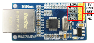
- 5V: This pin is used to supply power to the module. It requires a 5V DC power source.
- GND: The ground pin is connected to the ground reference of the power supply and the MCU for proper circuit operation.
- MISO (Master In Slave Out): This pin is used for data transmission from the module to the MCU. It carries data from the W5500 chip to the MCU during SPI communication.
- MOSI (Master Out Slave In): This pin is used for data transmission from the MCU to the module. It carries data from the MCU to the W5500 chip during SPI communication.
- SCK (Serial Clock): The SCK pin provides the clock signal for synchronizing data transmission between the module and the MCU during SPI communication.
- RST (Reset): The RST pin is used to reset the W5500 chip and the module. Pulling this pin LOW (or asserting it in a specific manner as defined by the module's datasheet) resets the chip to its initial state.
- SS (Slave Select): The SS pin is used to select the module as the target device for SPI communication. When the SS pin is LOW, it indicates that the MCU wants to communicate with the module.
- INT (Interrupt): The INT pin is an optional pin that can be used for receiving interrupt signals from the module. It can be configured to notify the MCU when specific events occur, such as receiving data or completing a transmission.
Applications:
- Internet of Things (IoT) Devices: The module can be used in IoT devices that need to connect to an Ethernet network for data exchange, remote monitoring, and control. Examples include smart home automation systems, environmental monitoring devices, industrial sensors, and more.
- Industrial Automation: In industrial settings, the module can enable communication between machines, control systems, and monitoring devices over an Ethernet network. It facilitates data collection, real-time control, and remote management of industrial processes.
- Networked Robotics: The module can be used in robotics applications where multiple robots need to communicate with each other or with a central control system over an Ethernet network. It allows for coordinated actions, data sharing, and centralized control.
- Embedded Systems: The module can be integrated into various embedded systems where Ethernet connectivity is required. This includes applications such as networked displays, vending machines, access control systems, and more.
- Data Acquisition and Logging: The module can enable data acquisition from sensors, devices, or equipment and transfer the collected data to a remote server or database for logging and analysis. It is useful in applications such as environmental monitoring, energy management, and scientific data collection.
- Remote Monitoring and Control: The module can be used to create systems for remote monitoring and control of devices or processes over an Ethernet network. It allows users to access and manage devices or systems from a remote location, enabling remote diagnostics, troubleshooting, and control.
- Ethernet-based Communication Protocols: The module can be utilized in systems that rely on Ethernet-based communication protocols, such as Modbus TCP/IP, MQTT, or OPC UA. It provides the necessary connectivity to enable seamless integration with these protocols, facilitating interoperability and data exchange with other devices and systems.
- Networked Audio/Video Streaming: The module can support applications involving networked audio and video streaming. It enables the transmission of multimedia content over Ethernet networks, making it suitable for applications like IP cameras, media players, and video conferencing systems.
Circuit:
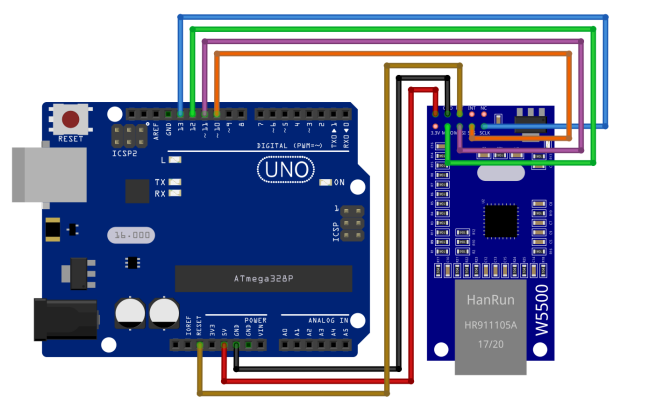
Module Pin > Uno Pin
5V > 5V Red
GND > GND Black
RST > RESET Brown
MISO > D12 Green
MOSI > D11 Purple
SCS (SS) > D10 Orange
SCLK > D13 Blue
Library:
The needed Libraries are preinstalled ones.
Code:
an example code that listens for client requests sent from a browser and prints the request on the serial monitor:
-
Network Configuration:
- Modify the following lines in the code to configure the network settings:
byte mac[] = { 0xDE, 0xAD, 0xBE, 0xEF, 0xFE, 0xED };(MAC address of the module)IPAddress ip(192, 168, 1, 100);(IP address of the module)
- Modify the following lines in the code to configure the network settings:
-
Upload the Code:
- Select the appropriate board and port from the Arduino IDE's Tools menu.
- Click on the "Upload" button to compile and upload the code to your Arduino Uno.
#include "SPI.h"
#include "Ethernet.h"

// Network configuration
byte mac[] = { 0xDE, 0xAD, 0xBE, 0xEF, 0xFE, 0xED }; // MAC address of the module
IPAddress ip(192, 168, 1, 100); // IP address of the module
EthernetServer server(80); // Port for server communication (HTTP)

void setup() {
  // Initialize Ethernet library
  Ethernet.begin(mac, ip);
  server.begin();

  // Print the assigned IP address of the module
  Serial.begin(9600);
  Serial.print("Module IP address: ");
  Serial.println(Ethernet.localIP());
}

void loop() {
  // Check for client connections
  EthernetClient client = server.available();
  if (client) {
    // New client connected
    Serial.println("New client connected");

    // Read the request from the client
    String request = client.readStringUntil('\r');
    Serial.println(request);

    // Close the connection
    client.stop();
    Serial.println("Client disconnected");
  }
}
-
Monitor Serial Output:
- After uploading the code, open the Serial Monitor in the Arduino IDE.
- Set the baud rate to 9600 baud.
- Ensure that the "Newline" or "Both NL & CR" option is selected at the bottom of the Serial Monitor.
- Wait for the message "Module IP address:
" to appear. This indicates that the module has been assigned an IP address.
-
Test with a Browser:
- On a device connected to the same network as the module, open a web browser.
- Enter the assigned IP address of the module in the browser's address bar and press Enter.
- The browser will send a request to the module, and the request will be displayed on the Serial Monitor.
You should now see the incoming requests from the browser displayed on the Serial Monitor. Each time you refresh the browser page or access the module's IP address, a new request will be shown.
Technical Details:
- chip type: W5500
- Supports both 3.3V & 5V.
- Hardwired TCP/IP Protocols: TCP, UDP, ICMP, IPv4, ARP, IGMP, PPPoE
- 10BaseT/100BaseTX Ethernet PHY embedded
- Supports automatic response (full duplex/half duplex mode)
- Supports 8 independent sockets simultaneously
- Internal 32Kbytes Memory for Tx/Rx Buffers
- Power off mode: support
- Network wake: support
- SPI interface (SPI MODE 0, 3), convenient connection with MCU
- Size: 55mm x 28mm
- Color: Blue
Resources:
Comparisons:
The W5500 and W5100 are both Ethernet network modules, but they differ in terms of features and capabilities. the next is a comparison between the two boards:
-
Chip Type:
- W5500: The W5500 board is based on the W5500 chip, which is a newer and more advanced version compared to the W5100.
- W5100: The W5100 board is based on the W5100 chip, which is an older generation chip.
-
Communication Speed:
- W5500: The W5500 chip supports high-speed communication up to 80 Mbps.
- W5100: The W5100 chip supports communication up to 10 Mbps.
-
Memory:
- W5500: The W5500 chip has an internal 32Kbytes memory for Tx/Rx buffers, which provides a larger buffer size for data transmission.
- W5100: The W5100 chip has a smaller internal buffer size compared to the W5500.
-
Socket Support:
- W5500: The W5500 chip supports up to 8 independent sockets simultaneously, allowing for multiple concurrent connections.
- W5100: The W5100 chip supports up to 4 independent sockets.
-
Power Consumption:
- W5500: The W5500 chip is designed to be more power-efficient, consuming lower power during operation.
- W5100: The W5100 chip consumes slightly more power compared to the W5500.
-
Protocol Support:
- W5500: The W5500 chip supports a wide range of protocols, including TCP, UDP, ICMP, IPv4, ARP, IGMP, and PPPoE.
- W5100: The W5100 chip also supports these protocols but may have limited support or compatibility for certain protocols.
-
SPI Interface:
- W5500: The W5500 chip supports SPI interface with modes 0 and 3, allowing for convenient connection with the MCU.
- W5100: The W5100 chip also supports SPI interface but may have different SPI mode compatibility.