AED 14.50
Description
The ESP8266 ESP01 is a compact, low-cost Wi-Fi microcontroller module based onthe power of the Espressif ESP8266 chip. Designed for easy integration with other microcontrollers, this module provides a simple and cost-effective way to add Wi-Fi connectivity to a wide array of projects. Whether you're a hobbyist or a professional, the ESP8266 ESP01 offers robust functionality. It supports TCP/IP protocols for reliable data transmission, making it suitable for Internet of Things (IoT) applications. With its powerful Tensilica Xtensa LX3 processor, it can handle a range of tasks efficiently. Additionally, the ESP8266 ESP01's small form factor allows it to fit easily into various project designs.
Package Includes:
- 1 x ESP8266 ESP01 WiFi Module
Features:
- Microcontroller: The ESP8266 ESP01 is based on Espressif's ESP8266 microcontroller chip, providing a low-cost, powerful solution for a wide range of projects.
- Onboard Wi-Fi: One of the most notable features of the ESP8266 ESP01 is its onboard Wi-Fi connectivity. This allows other microcontrollers to easily connect to a Wi-Fi network and make simple TCP/IP connections.
- Dual Use: The ESP8266 ESP01 can be used as either a UART to Wi-Fi adapter or as a standalone microcontroller. This versatility makes it a popular choice for a wide range of hobbyist and professional projects.
- Processing Power: The ESP8266 ESP01 is powered by a Tensilica Xtensa LX3 processor, which provides adequate processing power for most applications.
- Cost-Effective: The low cost of the ESP8266 ESP01 makes it a popular choice for IoT projects where cost is a concern.
- Compact Form Factor: With a compact form factor of 18mm x 25.6mm x 3mm, the ESP8266 ESP01 is easy to integrate into a wide range of projects.
- TCP/IP Protocol Support: The ESP8266 ESP01 supports TCP/IP protocols for data transmission over the Internet, making it a popu+lar choice for IoT projects.
- Wide Range of Applications: From hobbyist projects to professional applications, the ESP8266 ESP01 is a versatile solution that is used in a wide range of projects.
Description:
The ESP8266 ESP01 is a compact, low-cost Wi-Fi microcontroller module based on the Espressif ESP8266 chip. It is designed for easy integration with various microcontrollers, providing a simple and affordable solution for adding Wi-Fi connectivity to a wide range of projects. The module includes an onboard Wi-Fi transceiver, allowing it to function as a UART to Wi-Fi adapter, enabling other microcontrollers to establish Wi-Fi connections and transmit data over the Internet using TCP/IP protocols. This feature makes it particularly well-suited for IoT (Internet of Things) applications, where remote control and monitoring of devices over the Internet is essential.
The ESP8266 ESP01 is not just a peripheral device; it can also operate as a standalone microcontroller. It is equipped with a Tensilica Xtensa LX3 processor, offering sufficient processing power to run complex applications independently. The module's compact form factor, affordability, and robust Wi-Fi capabilities have made it a favorite among hobbyists and professionals alike. It is commonly used in a variety of projects, from simple home automation systems to more complex industrial IoT solutions, due to its versatility and ease of use.
Principle of Work:
The ESP8266 ESP01 is a compact, low-cost microcontroller module developed by Espressif Systems, featuring advanced Wi-Fi capabilities. It is based on the ESP8266 microcontroller chip, which incorporates a powerful Tensilica Xtensa LX3 processor. This processor enables the ESP01 to execute complex firmware and perform a range of tasks, making it a versatile tool for both hobbyists and professionals working on Internet of Things (IoT) projects.
Core Functionality
At its core, the ESP8266 ESP01 serves as a microcontroller with built-in Wi-Fi. It operates by executing firmware stored in its flash memory. This firmware implements the Wi-Fi stack and supports various communication protocols, including TCP/IP and HTTP, allowing the module to connect to a Wi-Fi network and communicate with other devices over the internet.
- Wi-Fi Connectivity: The ESP01 features an onboard Wi-Fi radio, which provides the capability to connect to Wi-Fi networks. This allows the ESP01 to perform tasks such as data transfer to cloud services, device control over the internet, or integration with other networked devices.
- Firmware Execution: The firmware, which resides in the module’s flash memory, defines the ESP01’s functionality. This includes the implementation of the Wi-Fi stack and communication protocols that manage data exchange between the module and the internet.
- Data Transmission: Once connected to a Wi-Fi network, the ESP01 can send and receive data. This capability is essential for IoT applications, where devices often need to communicate with remote servers or other networked devices.
Programming the ESP8266 ESP01
The ESP8266 ESP01 can be programmed in two primary modes:
-
Using Arduino IDE
- Overview: The Arduino Integrated Development Environment (IDE) provides a straightforward way to develop and upload code to the ESP01. By installing the ESP8266 board package, users can write and upload Arduino sketches that directly control the ESP01’s functions.
- Programming Process: In this setup, the ESP01 can be used as a standalone microcontroller. Users write code in the Arduino IDE to interact with the ESP01’s GPIO pins, configure Wi-Fi settings, and implement applications such as web servers or data logging.
- Code Deployment: The IDE facilitates writing, compiling, and uploading code through a USB-to-Serial adapter or an FTDI adapter, which connects to the ESP01’s RX, TX, VCC, and GND pins.
-
Using AT Commands (UART to Wi-Fi Adapter Mode)
- Overview: In this mode, the ESP01 functions as a UART-to-Wi-Fi adapter. The module communicates with another microcontroller through serial AT commands, which are used to configure the Wi-Fi settings, manage network connections, and perform simple TCP/IP operations.
- Programming Process: Here, users send AT commands via a serial interface to control the ESP01. This approach does not require the Arduino IDE and instead relies on a serial terminal program to interact with the module.
Advantages of the ESP8266 ESP01
The ESP8266 ESP01 offers several benefits for IoT projects and general applications:
- Wi-Fi Capabilities: The onboard Wi-Fi module enables both station and access point modes, making it adaptable for a variety of networking scenarios.
- Cost-Effective: Its low price point makes it an accessible option for both hobbyist and professional projects.
- Compact Size: The small form factor of the ESP01 allows it to be integrated into compact devices and projects.
- Powerful Processing: The Tensilica Xtensa LX3 processor provides ample computing power for running complex applications and managing network communication.
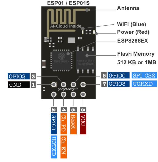
Pinout of the Module:
| Pin | Function | Description | Alternative Uses | Notes |
| GPIO0 | Boot Mode Selector / General I/O | Used to determine the device's boot mode. When pulled low during boot, it enters "UART Download" mode. | Digital I/O (Input/Output) |
Ensure GPIO0 is high for normal boot or low for firmware updates.
|
| GPIO2 | General I/O | Can be configured as a digital input or output pin. | Digital I/O (Input/Output) |
Often used for general purposes, such as interfacing with sensors or actuators.
|
| GPIO4 | General I/O | Can be used as a digital input or output pin. | Digital I/O (Input/Output) |
Also used for communication with peripherals in some applications.
|
| GPIO5 | Flash Chip Interface / General I/O | Primarily used for the flash memory chip interface, but can be used as a general-purpose I/O pin. | Digital I/O (Input/Output) |
Used in flash operations but available for general purposes when not in use.
|
| RX (GPIO3) | Serial Communication - Receive | Used for receiving data in serial communication (UART RX). | UART RX (Receive Data) |
Connect to TX of another device for serial data reception.
|
| TX (GPIO1) | Serial Communication - Transmit | Used for transmitting data in serial communication (UART TX). | UART TX (Transmit Data) |
Connect to RX of another device for serial data transmission.
|
| GND | Ground | Common ground connection for the module. | - |
Connect to the ground of the power source or other connected devices.
|
| VCC | Power Supply | Provides 3.3V power to the module. | - |
The module requires a stable 3.3V power supply. Do not connect to 5V, as it may damage the module.
|
Applications:
- Wi-Fi connectivity: The onboard Wi-Fi capability of the ESP8266 ESP01 makes it a popular choice for adding Wi-Fi connectivity to projects and devices that previously lacked it.
- Internet of Things (IoT) applications: The ESP8266 ESP01 can be used as a microcontroller that can connect to a Wi-Fi network and communicate with other IoT devices, such as sensors and actuators.
- Smart home automation: The ESP8266 ESP01 can be used to create home automation systems that can be controlled remotely over Wi-Fi, such as smart lighting and heating systems.
- Wireless data logging: The ESP8266 ESP01 can be used to collect data from sensors and transmit it wirelessly to a central repository for analysis.
- Wi-Fi-enabled projects: The ESP8266 ESP01 can be used to add Wi-Fi functionality to various projects, such as robots, drones, and other hobbyist or educational projects.
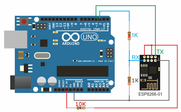
Circuit:
to connect the ESP8266 to Arduino Follow these steps.
- connect both ESP's VCC/3.3V/Power Pin and Enable Pin (red wires) to 10K resistor then to Uno's +3.3V power pin.
- connect ESP's Ground/GND Pin (Black Wire) to Uno's Ground/GND Pin.
- connect ESP's TX (green wire) to Uno's Pin 3
- connect ESP's RX (blue wire) to 1K resistor then to Uno's Pin 2.
- connect ESP's RX (blue wire) to 1K resistor and then to Uno's GND Pin
Library:
After uploading the code in the code section and connecting the last circuit:
set up your ESP8266 Wifi, follow these steps:
- Download the TCP Client app for Android. You can use any app available in the Play Store, but I recommend using TCP Client by Sollae Systems.
- Connect your phone to the ESP8266 Wifi. If it does not appear in the list of available networks, ensure that your Arduino is running and everything is connected correctly. If there are issues, refer to the ESP documentation for troubleshooting. The name of the wifi will typically start with "ESP" followed by the version name.
- Once connected, find the static IP address. You can do this by going to the Wifi Settings on your phone and clicking on network info. The default IP address in AP mode is 192.168.4.1, but you can change it by following the Wifi. config() reference.
- Open the TCP Client app you downloaded earlier. Connect to the ESP by clicking the connect button and entering the ESP's IP and port 80.
- Wait for the TCP Console to say "Connected".
- Talk to you Arduino Uno via Smart Phone
Once connected send a request by typing the following code to TCP Client:
esp8266:
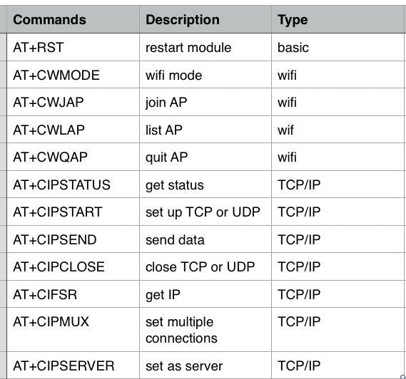
Check the AT Commands table attached to review the codes.
Or turn on the built-in LED using the command
LEDON
Or turn off the built-in LED using the command
LEDOFF
Or just say
HELLO
You can change what response from what you send depending on the logic you put into the code.
Code:
This is an Arduino sketch code that communicates with an ESP8266 Wi-Fi module over a serial interface. The code sets the ESP8266 as an access point, gets its IP address, enables multiple connections, and turns on a server on port 80. It listens to incoming messages on the serial port and performs various actions depending on the message, such as sending AT commands to the ESP8266 or turning on or off the built-in LED on the Arduino. The code also has functions to read incoming messages from the serial port, match strings, and send data to the ESP8266.
#include "SoftwareSerial.h"
SoftwareSerial wifiSerial(2, 3); // RX, TX for ESP8266
bool DEBUG = true; //show more logs
int responseTime = 10; //communication timeout
void setup()
{
 pinMode(13,OUTPUT); //set build in led as output
 // Open serial communications and wait for port to open esp8266:
 Serial.begin(115200);
 while (!Serial) {
 ; // wait for serial port to connect. Needed for Leonardo only
 }
 wifiSerial.begin(115200);
 while (!wifiSerial) {
 ; // wait for serial port to connect. Needed for Leonardo only
 }
 sendToWifi("AT+CWMODE=2",responseTime,DEBUG); // configure as access point
 sendToWifi("AT+CIFSR",responseTime,DEBUG); // get ip address
 sendToWifi("AT+CIPMUX=1",responseTime,DEBUG); // configure for multiple connections
 sendToWifi("AT+CIPSERVER=1,80",responseTime,DEBUG); // turn on server on port 80
 sendToUno("Wifi connection is running!",responseTime,DEBUG);
}
void loop()
{
 if(Serial.available()>0){
 String message = readSerialMessage();
 if(find(message,"debugEsp8266:")){
 String result = sendToWifi(message.substring(13,message.length()),responseTime,DEBUG);
 if(find(result,"OK"))
 sendData("\nOK");
 else
 sendData("\nEr");
 }
 }
 if(wifiSerial.available()>0){
 String message = readWifiSerialMessage();
 if(find(message,"esp8266:")){
 String result = sendToWifi(message.substring(8,message.length()),responseTime,DEBUG);
 if(find(result,"OK"))
 sendData("\n"+result);
 else
 sendData("\nErrRead"); //At command ERROR CODE for Failed Executing statement
 }else
 if(find(message,"HELLO")){ //receives HELLO from wifi
 sendData("\\nHI!"); //arduino says HI
 }else if(find(message,"LEDON")){
 //turn on built in LED:
 digitalWrite(13,HIGH);
 }else if(find(message,"LEDOFF")){
 //turn off built in LED:
 digitalWrite(13,LOW);
 }
 else{
 sendData("\nErrRead"); //Command ERROR CODE for UNABLE TO READ
 }
 }
 delay(responseTime);
}
/*
* Name: sendData
* Description: Function used to send string to tcp client using cipsend
* Params:
* Returns: void
*/
void sendData(String str){
 String len="";
 len+=str.length();
 sendToWifi("AT+CIPSEND=0,"+len,responseTime,DEBUG);
 delay(100);
 sendToWifi(str,responseTime,DEBUG);
 delay(100);
 sendToWifi("AT+CIPCLOSE=5",responseTime,DEBUG);
}
/*
* Name: find
* Description: Function used to match two string
* Params:
* Returns: true if match else false
*/
boolean find(String string, String value){
 return string.indexOf(value)>=0;
}
/*
* Name: readSerialMessage
* Description: Function used to read data from Arduino Serial.
* Params:
* Returns: The response from the Arduino (if there is a reponse)
*/
String readSerialMessage(){
 char value[100];
 int index_count =0;
 while(Serial.available()>0){
 value[index_count]=Serial.read();
 index_count++;
 value[index_count] = '\0'; // Null terminate the string
 }
 String str(value);
 str.trim();
 return str;
}
/*
* Name: readWifiSerialMessage
* Description: Function used to read data from ESP8266 Serial.
* Params:
* Returns: The response from the esp8266 (if there is a reponse)
*/
String readWifiSerialMessage(){
 char value[100];
 int index_count =0;
 while(wifiSerial.available()>0){
 value[index_count]=wifiSerial.read();
 index_count++;
 value[index_count] = '\0'; // Null terminate the string
 }
 String str(value);
 str.trim();
 return str;
}
/*
* Name: sendToWifi
* Description: Function used to send data to ESP8266.
* Params: command - the data/command to send; timeout - the time to wait for a response; debug - print to Serial window?(true = yes, false = no)
* Returns: The response from the esp8266 (if there is a reponse)
*/
String sendToWifi(String command, const int timeout, boolean debug){
 String response = "";
 wifiSerial.println(command); // send the read character to the esp8266
 long int time = millis();
 while( (time+timeout) > millis())
 {
 while(wifiSerial.available())
 {
 // The esp has data so display its output to the serial window
 char c = wifiSerial.read(); // read the next character.
 response+=c;
 }
 }
 if(debug)
 {
 Serial.println(response);
 }
 return response;
}
/*
* Name: sendToUno
* Description: Function used to send data to Arduino.
* Params: command - the data/command to send; timeout - the time to wait for a response; debug - print to Serial window?(true = yes, false = no)
* Returns: The response from the esp8266 (if there is a reponse)
*/
String sendToUno(String command, const int timeout, boolean debug){
 String response = "";
 Serial.println(command); // send the read character to the esp8266
 long int time = millis();
 while( (time+timeout) > millis())
 {
 while(Serial.available())
 {
 // The esp has data so display its output to the serial window
 char c = Serial.read(); // read the next character.
 response+=c;
 }
 }
 if(debug)
 {
 Serial.println(response);
 }
 return response;
}
Technical Details:
- Wi-Fi Direct (P2P), soft-AP
- 802.11 b/g/n
- Integrated TCP/IP protocol stack
- Integrated TR switch, balun, LNA, power amplifier, and matching network
- Integrated PLLs, regulators, DCXO, and power management units
- +19.5dBm output power in 802.11b mode
- Power down leakage current of <10uA
- 1MB Flash Memory
- SDIO 1.1 / 2.0, SPI, UART
- STBC, 1×1 MIMO, 2×1 MIMO
- A-MPDU & A-MSDU aggregation & 0.4ms guard interval
- Wake up and transmit packets in < 2ms
- Standby power consumption of < 1.0mW (DTIM3)
Resources:
Comparisons:
ESP01 and NodeMCU v1 are both microcontroller modules based on the ESP8266 chip. However, they have some differences:
- Form factor: ESP01 is a smaller module with only two GPIOs, while NodeMCU v1 is a development board that comes with more pins, including GPIOs, a USB port for power and data transfer, and micro-USB for programming.
- On-board memory: ESP01 has limited memory (1 MB), while NodeMCU v1 has more memory (4 MB).
- Wi-Fi capabilities: Both modules have Wi-Fi capabilities, but NodeMCU v1 has a better antenna design and is capable of longer-range Wi-Fi connections.
- User-friendliness: NodeMCU v1 is easier to use and set up, as it has a built-in micro-USB port for programming and debugging, while ESP01 requires an external USB-to-Serial converter.
NodeMCU v1 is a better option for projects that require more GPIOs, better Wi-Fi capabilities, and ease of use, while ESP01 is a good option for projects that have limited space or need only a few GPIOs.