AED 5.78
Description
The Encoder Photoelectric Speed Sensor Module LM393 is a small module that includes an LM393 main chip and an encoder with a slot width of 10mm. It operates on a DC 5V voltage and has a compact size of 32mm x 11mm x 20mm. The module also features PCB mounting holes with a distance of 15mm and a screw size of M3. It is designed to detect the speed and direction of a rotating object through the use of an optical encoder.
Package Includes:
- 1 x Encoder Photoelectric Speed Sensor Module LM393
Features:
- LM393 chip: The module is built with the LM393 chip which is a voltage comparator that has two independent low-current open-collector outputs.
- Photoelectric sensor: It uses a photoelectric sensor to detect changes in light and dark.
- Working voltage: The module works on a DC 5V voltage.
- LED indicator: It has a built-in LED indicator that indicates the presence of power and output status.
- PCB mounting holes: The module has two mounting holes that allow for easy attachment to a PCB or other surface.
- Compact size: The module has a small size of 32mm x 11mm x 20mm, making it suitable for applications with limited space.
Description:
The Encoder Photoelectric Speed Sensor Module LM393 black is a highly sensitive sensor module that is designed to detect rotational speed and position. It is commonly used in a variety of industrial and DIY projects, including robotics, automation, and control systems. The module operates by using a photoelectric sensor to detect the movement of an object. As the object moves past the sensor, it blocks or reflects the light, causing a change in the output signal. This signal is then processed by the LM393 chip, which provides a high or low signal output depending on the position and speed of the object. One of the key advantages of this sensor module is its high sensitivity, which allows it to detect even very small changes in position and speed. It also has a wide operating voltage range of 3.3V to 5V, making it compatible with a range of microcontrollers and other devices. The module features a compact and durable design, with PCB mounting holes and M3 screws for easy installation. It also has a low power consumption, making it ideal for battery-powered applications.
Principle of Work:
The LM393 Infrared Speed Sensor module is equipped with an infrared LED emitter and an infrared receiver that detect the light reflected back from a surface. The module operates by emitting an infrared signal towards the surface and then detecting the reflection of this signal by the receiver. The intensity of the reflected signal is proportional to the distance between the sensor and the surface, which enables the module to measure the speed of a moving object. To use the module, you would typically connect the power supply to the VCC and GND pins, respectively, and then connect the output signal to a microcontroller or other digital device. The module is designed to operate with a broad range of voltages, typically ranging between 3.3V and 5V. To detect the speed of a rotating object, you need to write a program that reads the digital signal on the digital input pin connected to the OUT pin of the module. The signal is either high or low, depending on whether the object is rotating or not. By counting the number of high signals in a given time period, you can calculate the speed of the rotating object.
Pinout of the Module:
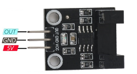
- VCC: Module power supply – 3-5.5 V
- GND: Ground
- OUT: Digital output data to the microcontroller
Applications:
- Measuring the speed of a rotating object, such as a motor or wheel.
- Object detection and counting in production lines.
- Automation systems, such as controlling conveyor belts or sorting systems.
- Automotive applications, such as speedometers and odometers.
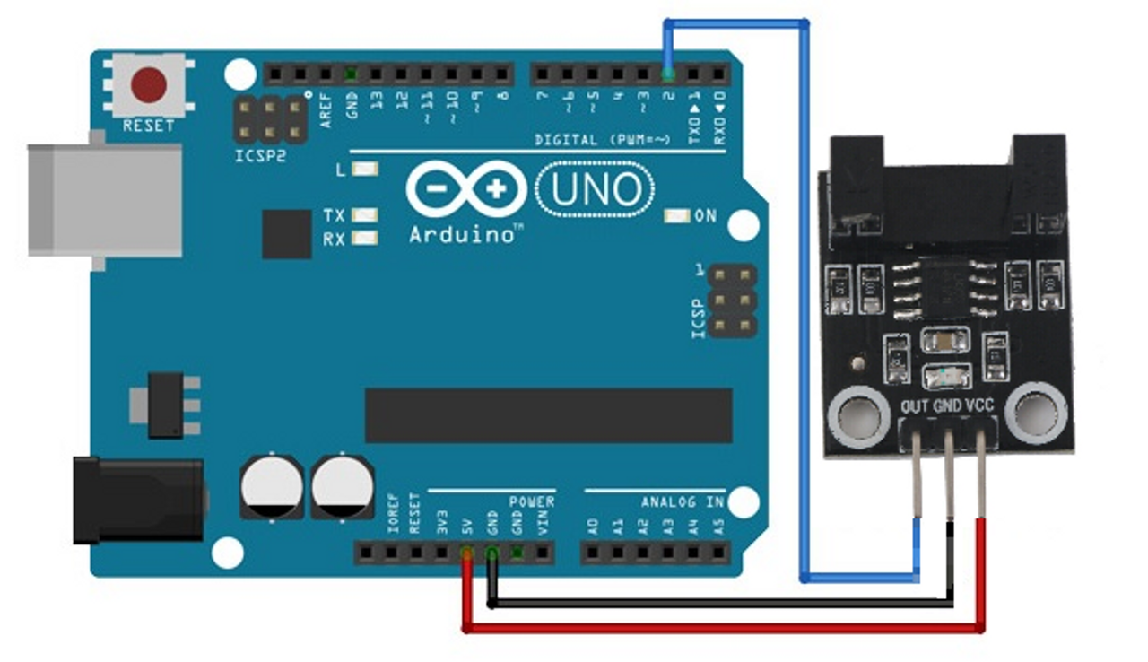
Circuit:
To use the code, you would need to connect the LM393 module to your Arduino board. The VCC and GND pins of the module should be connected to the 5V and GND pins of the Arduino board, respectively. The output pin of the module should be connected to digital pin 2 of the Arduino board.
Library:
To install the Timer library on Arduino IDE, follow these steps:
- Download the Timer library from the GitHub repository (https://github.com/brunocalou/Timer).
- Extract the downloaded zip file to a folder named "Timer".
- Open the Arduino IDE and go to Sketch -> Include Library -> Add .ZIP Library.
- Navigate to the Timer folder and select it.
- The Timer library should now be installed and ready to use. To include it in your sketch, go to Sketch -> Include Library -> Timer.
You can also directly install the Timer library using the Arduino IDE's Library Manager. To do this:
- Open the Arduino IDE and go to Sketch -> Include Library -> Manage Libraries.
- In the Library Manager, search for "Timer".
- Select the Timer library from the search results.
- Click on the "Install" button to install the library.
- The Timer library should now be installed and ready to use. To include it in your sketch, go to Sketch -> Include Library -> Timer.
Code:
The code you provided is used to measure the RPM (revolutions per minute) of a rotating object using an LM393 infrared speed sensor module and an Arduino board. Once the connections are made, upload the code to the Arduino board and open the Serial Monitor. The code will start measuring the RPM of the rotating object and print the value to the Serial Monitor every second. This code can be used in various applications where the RPM of a rotating object needs to be measured, such as in industrial machinery, robotics, and automation systems.
// Stepper motor control with ULN2003 driver and Arduino

#include "Stepper.h"

// Define the number of steps per revolution
const int stepsPerRevolution = 2048;

// Initialize the stepper motor
Stepper myStepper(stepsPerRevolution, 11, 10, 9, 8);

void setup() {
  // Set the speed of the stepper motor (in RPM)
  myStepper.setSpeed(10);

  // Initialize the serial communication
  Serial.begin(9600);
}

void loop() {
  // Wait for serial input
  while (!Serial.available());

  // Read the serial input
  char command = Serial.read();

  // Perform the appropriate action based on the serial input
  switch (command) {
    case 'F':
      Serial.println("Moving forward");
      myStepper.step(stepsPerRevolution / 4);
      break;
    case 'B':
      Serial.println("Moving backward");
      myStepper.step(-stepsPerRevolution / 4);
      break;
    case 'S':
      Serial.println("Stopping");
      myStepper.step(0);
      break;
    default:
      Serial.println("Invalid command");
  }
}
- The connection is established by using the
digitalPinToInterrupt()function to attach an interrupt to the LM393 pin, which triggers thecount()function each time the signal on the pin rises. Thecount()function increments thecountervariable each time it is called, which is used to calculate the RPM of a rotating object. - The
setup()function initializes the interrupt, sets up serial communication with a baud rate of 115200, and initializes a timer to call theRPM()function every second. - The
RPM()function calculates the RPM of the rotating object by multiplying the number of counts recorded by thecountervariable in the previous second by 60 (the number of seconds in a minute), then prints the result to the serial monitor. Thecountervariable is then reset to zero for the next second of counting. - Finally, the
loop()function calls thetimer.update()function to allow the timer to trigger theRPM()function every second.
Technical Details:
- Optocoupler Model: H2010
- Optocoupler slot width: 10mm
- Main chip: LM393
- Working voltage: DC 5V
- PCB Mounting holes distance: 15mm
- Screw Size: M3
- Size: 32mm x11mm x 20mm
Resources:
Comparisons:
Encoder Photoelectric Speed Sensor Module LM393 and the Encoder Speed Optical Coupling Sensor Module FC-03 are infrared speed sensors that can detect the speed of a passing object using the interruption of an infrared beam.
However, there are some differences between the two sensors:
- Pinout: Encoder Photoelectric Speed Sensor Module LM393 has 3 pins, while the other sensor has 4 pins. This means that the wiring and pin configuration for each sensor may differ.
- Output: The Encoder Photoelectric Speed Sensor Module LM393 appears to output a digital signal when the infrared beam is interrupted, while the Encoder Speed Optical Coupling Sensor Module FC-03 outputs an analog signal that varies depending on the intensity of the interrupted infrared beam. This means that Encoder Photoelectric Speed Sensor Module LM393 is better suited for detecting whether an object has passed a certain point or not, while the Encoder Speed Optical Coupling Sensor Module FC-03 can be used to measure the speed of a passing object.