Out Of Stock
Description
The MAX471 Sensor is a versatile and precise current sensing solution that allows you to monitor both charge and discharge currents in a wide range of applications. This high-side current sensing module is equipped with a precision internal sense resistor and provides the capability to sense currents up to 3A using its internal resistor (MAX471) or even higher currents with an external sense resistor (MAX472). Whether you are involved in energy management or various other applications, the MAX471 Sensor empowers you with accurate current monitoring and measurement capabilities.
Package Includes:
- 1x Current Sensor Module MAX471 DC Blue
Features:
- Dual Monitoring - Charge and Discharge: The MAX471 Sensor is designed to monitor both charge and discharge currents, making it ideal for applications that require comprehensive current sensing.
- Complete High-Side Current Sensing: This sensor operates on the high side of the circuit, enabling accurate current measurements without disrupting the ground connection, ensuring minimal interference with your circuit's functionality.
- Precision Internal Sense Resistor: Inside the IC, there is a high-precision 35 milliohm shunt resistor dedicated to current measurement. This ensures precise and reliable current measurements for your applications.
- Wide Input Voltage Range: The MAX471 Sensor can accept input voltages ranging from 3V to 36V, making it suitable for a broad spectrum of voltage levels commonly encountered in electronic systems.
- Flexible Current Sensing Options: With the MAX471, you can sense currents up to 3A using the internal sense resistor, making it a capable choice for various low to moderate-current applications. If your application demands higher current sensing capabilities, you can use an external sense resistor with the MAX472 variant.
- Versatile Microcontroller Connectivity: The sensor provides four pins (RS-, RS+, and two additional pins) for seamless connectivity with a microcontroller or other control systems, ensuring easy integration into your projects.
- Positive Output Voltage: Regardless of the direction of current flow, the MAX471 Sensor always provides a positive voltage at the OUT pin. This simplifies data processing and interpretation, enhancing overall usability.
Description:
the MAX471 Sensor – a cutting-edge solution for comprehensive current monitoring in a vast array of applications. This high-precision, high-side current sensing module redefines the way you measure and manage charge and discharge currents. With its broad input voltage range of 3V to 36V, the MAX471 Sensor accommodates diverse voltage levels encountered in electronics, offering unrivaled flexibility. At its core, this sensor features a precision 35 milliohm shunt resistor, ensuring accurate and reliable current measurements. Whether you seek to optimize energy management, enhance battery health, or implement motor control, the MAX471 Sensor delivers. It provides seamless connectivity with microcontrollers through four pins, simplifying integration. Choose the MAX471 Sensor for its versatile current sensing options, allowing you to measure currents up to 3A with the internal resistor (MAX471) or even higher currents using an external sense resistor (MAX472). With this sensor, you'll always receive a positive voltage output at the OUT pin, ensuring hassle-free data interpretation. Welcome to the future of current sensing with the MAX471 Sensor.
Principle of Work:
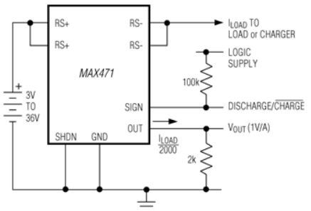
The MAX471/MAX472 are sophisticated, bidirectional high-side current-sense amplifiers meticulously engineered for applications such as portable computers, smartphones, and any other systems reliant on battery or DC power-line monitoring. These amplifiers offer a crucial advantage in battery-powered systems, as they don't disrupt the ground paths of the battery chargers or monitors frequently present in advanced "smart" battery setups.
Internally, the MAX471 incorporates an ingeniously designed 35-milliohm current-sense resistor, which plays a pivotal role in measuring battery currents of up to 3A. In the case of the MAX472, it takes versatility a step further by accommodating external sense and gain-setting resistors, making it well-suited for applications demanding higher current measurement capabilities or additional flexibility. Both of these devices produce a current output that can be effortlessly converted to a ground-referenced voltage with the aid of a single resistor. This innovative feature ensures compatibility with a broad spectrum of battery voltages and current levels, enhancing their adaptability across various scenarios. To provide valuable insights into the system's operation, the MAX471/MAX472 offers an open-collector SIGN output. This output conveniently indicates the direction of current flow, enabling users to discern whether a battery is currently being charged or discharged. these devices showcase a remarkable operational voltage range, spanning from 3V to 36V. Their efficiency is underscored by their low power consumption, drawing less than 100 microamperes over a wide temperature range. In the event of a shutdown, they exhibit a maximum shutdown current of 18 microamperes, enhancing their overall power-saving capabilities.
Pinout of the Board:
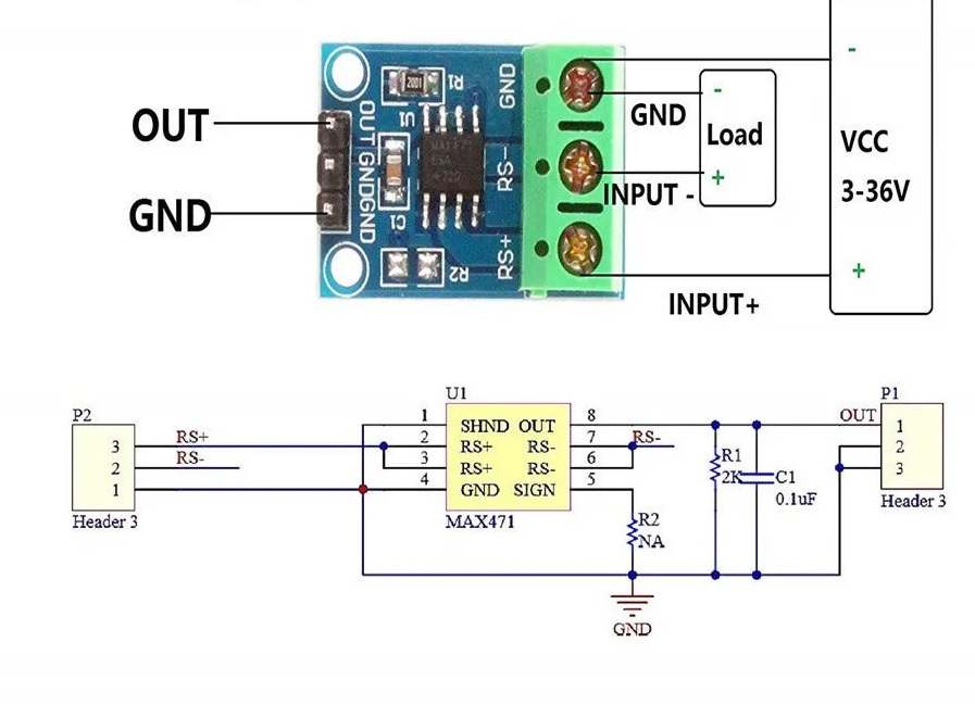
Input Connections:
- INPUT+ (RS+): This pin connects to the positive terminal of the power supply, specifically the positive side of the load power supply. It serves as the input point for the current to be monitored, allowing the module to sense current flow from the positive side of the load.
- INPUT- (RS-): This pin connects to the positive terminal of the load itself. It completes the current sensing circuit, enabling the module to accurately measure the current flowing through the load. This connection is essential for bidirectional current monitoring.
- GND (Ground): This pin is the ground connection for the module. It connects to the negative terminal of either the power supply or the load, establishing the common ground reference for the entire system.
Output Connections:
- OUT (Output Voltage): The OUT pin provides a voltage signal that corresponds to the detected current value. This voltage can be connected to the analog-to-digital (AD) input of a microcontroller or another data acquisition device. The output voltage is directly proportional to the detected current, with a 1VIA (1 Volt per Ampere) ratio. For instance, if the output voltage is 1V, it indicates that the detected current is 1A, making it a convenient way to interpret and record current data.
- GND (Ground): This GND connection is linked to the negative terminal of the microcontroller or data acquisition system. It ensures a common ground reference between the module and the connected microcontroller, facilitating accurate and reliable voltage measurements.
Applications:
- Battery Management: These modules are commonly used in battery-powered devices and systems to monitor charge and discharge currents. They help optimize battery performance, extend battery life, and ensure safe charging and discharging.
- Power Management: In power supply and distribution systems, these modules are utilized to monitor current flow, enabling precise control and management of power usage. This is crucial for energy-efficient designs.
- Motor Control: In motor control systems, such as robotics and automation, these modules provide accurate current feedback. This information is used to control motor speed, torque, and direction, ensuring efficient and safe motor operation.
- Overcurrent Protection: The modules are often integrated into circuits and systems to detect overcurrent conditions. When excessive current is detected, protective measures can be triggered, preventing damage to components and systems.
- Charging Systems: In battery charging applications, these modules help monitor the charging current, ensuring that batteries are charged safely and efficiently. They are commonly used in solar charge controllers and battery chargers.
- Smart Electronics: In smart devices and IoT applications, the modules enable real-time monitoring of current consumption. This data is valuable for optimizing device performance and battery life.
- Power Supplies: In adjustable power supply units, the modules assist in monitoring and controlling the output current. This is crucial for providing stable and regulated power to connected devices.
- Energy Management Systems: In larger-scale energy management systems, such as industrial automation and smart grids, these modules play a role in monitoring and optimizing power usage, contributing to energy efficiency and cost savings.
- Electronic Projects: Hobbyists and electronics enthusiasts often use these modules in DIY projects to measure and display current consumption in various applications, from LED lighting to small robotics.
- Automotive Applications: In vehicles, these modules can monitor various electrical systems, including battery charging, power distribution, and motor control. They contribute to the overall safety and performance of automotive electronics.
- Solar Power Systems: In solar energy systems, these modules help monitor the current generated by solar panels and the flow of energy into batteries or the grid, ensuring efficient energy conversion and storage.
- Home Automation: Current sensing modules can be used in home automation systems to monitor and control the power consumption of appliances and devices, making homes more energy-efficient.
Circuit:
- Signal Reading (A0): The A0 pin is used to capture the voltage signal generated by the module's OUT pin. This signal represents the current being monitored and can be read through the A0 analog input.
- Current Direction Indicator (SIGN): The SIGN pin functions as an open collector input. Its state changes depending on the direction of current flow within the circuit. When current flows from RS+ to RS-, the SIGN pin is in a closed state. Conversely, when the current flows in the opposite direction, the SIGN pin is open.
- Testing Current Direction: To determine the current direction, you can easily test it by connecting a pull-up resistor to the SIGN pin and using the
digitalReadfunction. If the SIGN pin reads HIGH or 1, it signifies that the current is flowing from RS+ to RS-. This intuitive feature simplifies the process of identifying the direction of current flow within the circuit, which is valuable for various monitoring and control applications.

Library:
No circuit needed.
Code:
The sketch is nothing more than a modified Simple Arduino Voltmeter for this device. It is very convenient with a scale factor of 1V per Amp. The values are displayed on the serial monitor. the code continuously reads the current sensor's output voltage, converts it to a current value, and displays that current value on the Arduino's serial monitor. This allows you to monitor the current flowing through the sensor in real-time:
// Define the analog input pin
const int currentSensorPin = A0;

// Variables for raw ADC value and current
int rawValue = 0;
float current = 0.0;

void setup() {
  // Set the current sensor pin as an input
  pinMode(currentSensorPin, INPUT);

  // Initialize the serial communication for debugging
  Serial.begin(9600);
}

void loop() {
  // Read the raw ADC value from the current sensor
  rawValue = analogRead(currentSensorPin);

  // Convert the raw ADC value to current in amps
  // Assuming a 5V reference voltage and 10-bit ADC resolution (1024 steps)
  current = (rawValue * 5.0) / 1024.0;

  // Print the current measurement with 3 decimal places
  Serial.print("Current = ");
  Serial.print(current, 3); // Displaying 3 digits after the decimal point
  Serial.println(" amps DC");

  // Add a delay for stability and to reduce serial output rate
  delay(200);
}
-
Initialization:
- It sets up a constant
currentSensorPinto represent the analog input pin A0. - It defines variables
rawValueto store the raw analog-to-digital conversion value andcurrentto store the calculated current value.
- It sets up a constant
-
Setup Function:
- In the
setup()function, it configures thecurrentSensorPinas an input. - It initializes serial communication with a baud rate of 9600 for debugging purposes.
- In the
-
Loop Function:
- Inside the
loop()function, it continuously performs the following steps:- Reads the analog voltage value from the current sensor connected to
currentSensorPinusinganalogRead(). This raw value represents the voltage proportional to the current being measured. - Converts the raw analog value to the corresponding current in amperes. The conversion is based on the assumption that the sensor operates with a 5V reference voltage and a 10-bit ADC resolution (1024 steps).
- Prints the calculated current value to the serial monitor with a precision of 3 decimal places.
- Adds a delay of 200 milliseconds to stabilize the readings and reduce the rate of serial output.
- Reads the analog voltage value from the current sensor connected to
- Inside the
Technical Details:
- Current sens max: +/- 3A
- 100µA Max Supply Current
- 18µA Max Shutdown Mode
- Current sense voltage: 3 to 36V
- Sensor output: 1V / Amp
- Dimensions: 24.3 * 17mm
Resources:
Comparisons:
The MAX471/MAX472 module and the ACS712 module are both current sensing solutions, but they have some differences in terms of features, working principles, and applications, both the MAX471/MAX472 and ACS712 modules are suitable for various applications. The choice between them depends on factors such as the required current range, the need for bidirectional sensing, the type of output (voltage or current), and the specific application's requirements for precision and isolation:
- Current Direction: The MAX471/MAX472 modules are bidirectional, meaning they can sense current flow in both directions, from RS+ to RS- and vice versa. This is useful for applications where current direction matters, such as battery charging and discharging monitoring.
- Voltage Output: These modules provide a voltage output that is proportional to the sensed current. The voltage can be read using an analog input on a microcontroller or another data acquisition device.
- Internal Shunt Resistor: The MAX471 module has an internal 35-milliohm shunt resistor, simplifying the circuit design for low to moderate current sensing applications.
- Wide Input Voltage Range: They can operate in a voltage range from 3V to 36V, making them suitable for various voltage levels commonly encountered in electronic systems.
- Usage: They are commonly used in applications such as battery management, power management, motor control, overcurrent protection, and energy management.
ACS712 Module:
- Current Direction: The ACS712 module is also bidirectional and can sense current flow in both directions.
- Output Type: Unlike the MAX471/MAX472 modules, the ACS712 provides an analog voltage output that varies linearly with the sensed current. It typically outputs 2.5V at zero current, making it suitable for bipolar current measurements.
- Variants: The ACS712 is available in different variants with current ratings ranging from 5A to 30A, allowing you to choose a module that matches your specific current measurement requirements.
- Hall Effect Sensor: The ACS712 module uses a Hall effect sensor to measure current, which is a contactless sensing method. This can be advantageous in applications where isolation between the current being measured and the measuring circuit is essential.
- Applications: ACS712 modules are commonly used in motor control, power inverters, robotics, and other applications where accurate and isolated current measurements are needed.