AED 32.00
Description
The HCMODU0099 module is an advanced breakout board designed to expand the number of Analog pins efficiently through the integration of the ADS1015 chip. This module is equipped with a 12-bit Analog-to-Digital Converter (ADC) featuring four channels, providing enhanced flexibility for a variety of applications.
Package Includes:
- 1 x 12Bit ADS1015 I2C Analog To Digital Converter Module
Features:
- ADS1015 Integration: The module utilizes the ADS1015 chip, a 12-bit ADC known for its precision and reliability.
- I2C Bus Interface: The ADS1015 chip on the module features an I2C bus interface, simplifying communication and ensuring compatibility with a range of devices.
- Selectable Addresses: The module allows users to choose from four selectable addresses based on the configuration of the ADDR pin. The default address is 0x48, applicable when ADDR is connected to GND.
- Multiple Input Channels: With four input channels, this breakout board supports a multiplexed configuration, enabling the monitoring of various analog signals.
- Wide Operating Temperature Range: The module operates reliably across a broad temperature range from -40 to 125 degrees Celsius, making it suitable for diverse environmental conditions.
Description:
The HCMODU0099 module stands as a sophisticated breakout board engineered to enhance the capabilities of microcontroller units (MCUs) by expanding the available Analog pins through seamless integration with the ADS1015 chip. This module serves as a pivotal component for applications demanding precise Analog-to-Digital Conversion (ADC) with the added flexibility of multiple channels. Designed with versatility in mind, the module operates within a broad temperature range, making it suitable for diverse environmental conditions. At its core, the ADS1015 chip within the module employs two distinctive conversion modes, allowing for tailored operation based on the specific needs of the application. The single-shot mode optimizes power consumption by initiating conversions upon request and powering down thereafter, ideal for systems requiring periodic measurements or featuring extended idle periods. In contrast, the continuous conversion mode facilitates real-time monitoring by consecutively converting input signals, ensuring a constant flow of updated data that can be accessed at any time. The module communicates with MCUs through the I2C bus, providing a standardized protocol for efficient data transfer. This integration allows for precise control over conversion modes, enabling the MCU to dictate whether single-shot or continuous conversion is most fitting for the application. The ability to read data from the internal conversion register ensures that the most recent and accurate conversion results are readily available for further processing.
Principle of Work:
The ADS1015 employs two conversion modes to cater to different application needs: single-shot and continuous conversion.
- Single-Shot Mode: In this mode, the ADS1015 converts the input signal upon request. Once the conversion is completed, the resulting value is stored in an internal conversion register. Subsequently, the module powers down, optimizing power consumption. This mode is particularly beneficial for systems that only require periodic conversions or experience extended idle periods between conversion tasks. The single-shot mode efficiently balances the need for precision with power efficiency.
- Continuous Conversion Mode: Contrasting with single-shot mode, continuous conversion mode offers a more dynamic operation. The ADC initiates the conversion of the input signal as soon as the previous conversion concludes. The rate of continuous conversion aligns with the programmed data rate, ensuring a steady flow of updated information. Data from the conversion can be read at any time, reflecting the most recent completed conversion. This model is well-suited for applications where real-time monitoring or frequent updates of the input signal are crucial.
Integration with MCU:
The HCMODU0099 module seamlessly interfaces with microcontroller units (MCUs) through the I2C bus. The MCU can initiate communication with the module, requesting a single conversion in single-shot mode or establishing a continuous conversion process for real-time monitoring.
- I2C Communication: The module utilizes the I2C protocol for communication with the MCU, providing a standardized and efficient means of data transfer.
- Control of Conversion Modes: The MCU can control the module's conversion modes, selecting between single-shot and continuous conversion based on the application requirements.
- Reading Data: Once a conversion is complete, the MCU can read the data from the internal conversion register, allowing for the retrieval of accurate analog-to-digital conversion results.
- Power Management: In single-shot mode, the MCU can strategically trigger conversions to optimize power consumption, ideal for battery-operated systems or applications with strict power efficiency requirements.
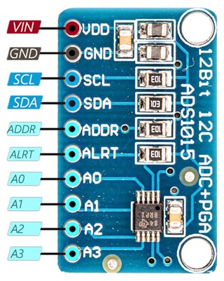
Pinout of the Module:
| Pin | Description |
|---|---|
| VCC | Module Power Supply |
| GND | Ground |
| SCL | I2C Clock Pin |
| SDA | I2C Data Pin |
| ADD | I2C Address Pin |
| ALRT | Data Ready Interrupt |
| A0-3 | Analog Inputs 0-3 |
- VCC (Module Power Supply): Provides power to the module.
- GND (Ground): Serves as the ground reference for the module.
- SCL (I2C Clock Pin): Connects to the clock line of the I2C bus for communication.
- SDA (I2C Data Pin): Connects to the data line of the I2C bus for bidirectional communication.
- ADDR (I2C Address Pin): Determines the I2C address of the module. Configuration of this pin sets the device's address.
- ALRT (Data Ready Interrupt): Generates an interrupt signal to indicate when data is ready for retrieval.
- A0-3 (Analog Inputs 0-3): These pins serve as the analog input channels for the module, allowing the conversion of analog signals to digital data. Each pin corresponds to a specific analog input channel.
Applications:
- Sensor Interface: The module is ideal for interfacing with analog sensors, such as temperature sensors, pressure sensors, or light sensors. It enables microcontrollers to accurately read and process data from these sensors.
- Data Acquisition Systems: In applications where real-time and accurate data acquisition is crucial, the module can be employed to convert analog signals into digital data, providing a reliable interface for data logging or monitoring systems.
- IoT (Internet of Things) Devices: The module's compact design and I2C interface make it suitable for IoT devices. It can be integrated into IoT nodes to facilitate the conversion of analog sensor data for transmission and analysis.
- Battery-Powered Systems: With its power-efficient single-shot mode, the module is well-suited for battery-operated devices. It enables periodic analog-to-digital conversions while optimizing power consumption during idle periods.
- Industrial Automation: In industrial settings, the module can be used to interface with analog sensors and transducers, providing precise measurements for control and monitoring systems.
- Test and Measurement Equipment: The high-resolution ADC and multiple input channels make the module valuable in test and measurement applications, where accurate analog signal conversion is critical.
- Embedded Systems: The module seamlessly integrates with microcontroller units in embedded systems, expanding the analog input capabilities and enhancing the overall functionality of the system.
- Prototyping and Development: Engineers and hobbyists can use the module for prototyping and developing electronic projects that involve analog sensors or require precise analog-to-digital conversion.
- Energy Monitoring: In energy monitoring applications, the module can be employed to measure and monitor analog signals related to power consumption, allowing for accurate energy usage analysis.
- Medical Devices: The precise analog-to-digital conversion capabilities make the module suitable for certain medical devices, such as patient monitoring systems or diagnostic equipment.
Circuit:
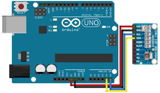
- 5V (Arduino) - VCC (Module Power Supply): Connect the 5V output from the Arduino to the VCC pin of the HCMODU0099 module to provide power to the module.
- GND (Arduino) - GND (Module Ground): Connect the GND (Ground) pin from the Arduino to the GND pin of the HCMODU0099 module, establishing a common ground reference.
- A4 (Arduino) - SDA (Module I2C Data Pin): Connect the A4 pin (SDA) on the Arduino to the SDA pin of the HCMODU0099 module. This facilitates bidirectional data transfer on the I2C bus.
- A5 (Arduino) - SCL (Module I2C Clock Pin): Connect the A5 pin (SCL) on the Arduino to the SCL pin of the HCMODU0099 module. This connection is essential for clock synchronization in I2C communication.
Library:
-
Download the Library ZIP File:
- Download the library from its source (Link) in ZIP format.
-
Open the Arduino IDE:
- Launch the Arduino IDE on your computer.
-
Navigate to Library Manager:
- In the Arduino IDE, go to "Sketch" in the menu bar, then select "Include Library" > "Manage Libraries..."
-
Library Manager:
- The Library Manager will open. Click on the "Install" button in the upper left corner.
-
Add Library from ZIP File:
- At the top of the Library Manager window, there's an icon that looks like an open book. Click on it to reveal a drop-down menu.
- Choose "Add. ZIP Library..."
-
Select the ZIP File:
- Navigate to the location where you downloaded the library ZIP file and select it.
- Click the "Open" button.
-
Installation:
- The Library Manager will automatically install the library. You'll see a progress bar and installation messages.
-
Close Library Manager:
- Once the installation is complete, close the Library Manager.
Code:
This code initializes communication with a potentiometer-based sensor connected to an ADS1115 module on an Arduino. It continuously reads analog values from four channels, calculates corresponding voltages, and prints the results to the serial monitor with a 1-second delay between readings. The ADS1115 is configured with a gain of 0 for optimal range.
#include "ADS1X15.h"

// Create an instance of the ADS1115 class with the I2C address 0x48.
ADS1115 ADS(0x48);

void setup()
{
  // Begin serial communication for debugging.
  Serial.begin(115200);

  // Print the name of the current file.
  Serial.println(__FILE__);

  // Print the version of the ADS1X15 library.
  Serial.print("ADS1X15_LIB_VERSION: ");
  Serial.println(ADS1X15_LIB_VERSION);

  // Initialize the ADS1115 module.
  ADS.begin();
}

void loop()
{
  // Set the gain to 0 for optimal range.
  ADS.setGain(0);

  // Read analog values from each channel.
  int16_t val_0 = ADS.readADC(0);
  int16_t val_1 = ADS.readADC(1);
  int16_t val_2 = ADS.readADC(2);
  int16_t val_3 = ADS.readADC(3);

  // Calculate the voltage factor.
  float voltageFactor = ADS.toVoltage(1);

  // Print the analog values and corresponding voltages for each channel.
  Serial.print("Analog0: "); Serial.print(val_0); Serial.print('\t'); Serial.print(val_0 * voltageFactor, 3);
  Serial.print("\tAnalog1: "); Serial.print(val_1); Serial.print('\t'); Serial.print(val_1 * voltageFactor, 3);
  Serial.print("\tAnalog2: "); Serial.print(val_2); Serial.print('\t'); Serial.print(val_2 * voltageFactor, 3);
  Serial.print("\tAnalog3: "); Serial.print(val_3); Serial.print('\t'); Serial.print(val_3 * voltageFactor, 3);
  Serial.println();

  // Delay for one second before the next reading.
  delay(1000);
}
Library Inclusion:
- The code includes the "ADS1X15.h" library, which is likely a library for the ADS1115 Analog-to-Digital Converter (ADC) chip.
ADS1115 Instance Creation:
- An instance of the
ADS1115class is created with the I2C address0x48, representing the ADS1115 module.
Setup Function:
- Serial communication is initiated for debugging purposes with a baud rate of 115200.
- The name of the current file and the version of the ADS1X15 library are printed to the serial monitor.
- The
begin()function is called on theADSobject to initialize the ADS1115 module.
Loop Function:
- The
loop()function is the main execution loop that continuously performs the following operations:- Sets the gain of the ADS1115 to 0, optimizing the measurement range.
- Reads analog values from four channels (0 to 3) using the
readADC()function. - Calculate the voltage factor using the
toVoltage()function with an argument of 1. - Prints the analog values and corresponding voltages for each channel to the serial monitor.
- Introduces a delay of 1 second using
delay(1000)before the next iteration.
Technical Details:
- Integral Nonlinearity (INL): 0.5 (+/- LSB)
- Resolution: 12 bits
- Maximum Sample Rate: 0.0033 MSPS (Mega Samples Per Second)
- Sample Rate (max): 3.3 kSPS (kilo Samples Per Second)
- Number of Input Channels: 4
- Analog Voltage AVDD (Max): 5.5V
- Analog Voltage AVDD (Min): 2V
- Operating Temperature Range: -40 to 125 degrees Celsius
- Digital Supply Voltage (Max): 5.5V
- Digital Supply Voltage (Min): 2V
- Power Consumption (Typical): 0.3 mW
- Input Range (Max): 5.5V
- Input Type: Differential, Single-Ended
- Interface: I2C
- Reference Mode: Internal Delta-Sigma Architecture
Resources:
Comparisons:
The ADS1015 and ADS1115 are both Analog-to-Digital Converters (ADCs) from Texas Instruments, and they share many similarities, the choice between the ADS1015 and ADS1115 depends on the specific requirements of your application. If you need higher resolution and precision in analog-to-digital conversion, the ADS1115 is a better choice, but it comes at the expense of increased power consumption:
-
Resolution:
- ADS1015: 12-bit resolution.
- ADS1115: 16-bit resolution.
-
Channels:
- Both modules support multiple channels, but the ADS1015 has four single-ended or two differential channels, while the ADS1115 has four differential channels.
-
Sample Rate:
- ADS1015: Up to 3300 samples per second (SPS).
- ADS1115: Maximum data rate is 860 SPS in single-shot mode, and programmable up to 860 SPS in continuous conversion mode.
-
I2C Address:
- Both modules have selectable I2C addresses through the ADDR pin. The default address for both is 0x48.
-
Power Consumption:
- ADS1015: Generally consumes less power compared to the ADS1115.
- ADS1115: Consumes more power due to its higher resolution.
-
Applications:
- ADS1015: Suitable for applications where lower resolution is acceptable, and power efficiency is crucial.
- ADS1115: Ideal for applications that require higher precision in analog-to-digital conversion, even at the cost of increased power consumption.
-
Use Cases:
- ADS1015: Commonly used in battery-powered devices, low-power sensors, and applications where precision is not the primary concern.
- ADS1115: Preferred in applications where high-resolution and accurate analog measurements are essential, such as industrial sensors, data acquisition systems, and medical instruments.
-
Voltage Reference:
- Both modules support an internal voltage reference, but the ADS1115 has a programmable gain amplifier (PGA) that allows you to adjust the input range.